New Exploration Concepts for the Edwards and Sligo Margins, Cretaceous of Onshore Texas1
Dale A. Fritz,2 Terry W. Belsher,3 James M. Medlin,3 John L. Stubbs,3 Robert P. Wright,3 and Paul M. (Mitch) Harris4
Search and Discovery Article #10013 (2001)
1Adaptation for online presentation of article of
the same title by same authors published in AAPG Bulletin, v. 84, no. 7 (July,
2000), p. 905-922.
2Chevron U.S.A. Production Company, Houston,
Texas. Present address: Santa Fe Snyder Corporation, Houston, Texas.
3Chevron U.S.A. Production Company, Houston,
Texas.
4Chevron Petroleum Technology Company, Houston,
Texas.
We examined the potential in onshore Texas of the most prolific reservoirs found to date in the Gulf of Mexico basin, Cretaceous carbonates, and in particular the Edwards and Sligo formations. Two-dimensional (2-D) and three-dimensional (3-D) seismic data with lithologic and biostratigraphic information led to a detailed sequence stratigraphic framework. This framework resulted in a concentrated exploration effort in Lavaca County, a redefinition of the Edwards shelf margin, and confirmation of a major sequence boundary in the Sligo.
The youngest Edwards margin appears to have stepped seaward a distance of more than 3 mi (4.8 km) from the position of the margin as indicated by the Word field. This seaward shift and repositioning of the margin is shown in 3-D seismic and well data. Recognized within the progradational package are distal slope wackestones, reef and bank complexes, and back-reef lagoonal deposits that are offset seaward across sequence boundaries. Reef and grainstone deposits are located far seaward of the commonly recognized margin and numerous exposure surfaces occur in the shelf deposits. Proximity to faulting after burial ensures the development of a plumbing system that enhances secondary porosity and provides a migration pathway for hydrocarbons.
A Sligo debris play is based on a sequence boundary within the upper part of the Sligo in ferred from seismic geometry and surface exposures in Mexico. The seismic portrays a wedge geometry positioned downslope from the Sligo margin. Base-level change about the sequence boundary would have initiated coarse carbonate debris- and grain-flow deposition seaward of the Sligo shelf margin. Rapid deposition may have helped preserve porosity within the thick debris wedge. Data from reservoir analogs confirm that downslope carbonates can retain reservoir-quality porosity. Facies variation and slump faulting on the foreslope creates the potential for trapping, and juxtaposition to deep-water carbonates sets up the source and migration pathway. This undrilled wedge extends for hundreds of miles along the Sligo margin.


Click here to view sequence and overlay of Figure 8 and Figure 10.
![]() Figure
9--Three-dimensional seismic user track line of Figure 7
shows details of the
Edwards stratigraphy. The line location is also shown on Figure
3. Three wells
located on the seismic line are correlated on the cross section of Figure
10.
The Mobil 1 Kahanek well is projected from Word field approximately 13 mi (21
km) along the strike of the published Edwards margin. The Chevron 1 Coby well
and the Exxon 1 Zaruba well are located on the line as is shown on Figure
7. The
112 Ma sequence boundary of Goldhammer et al. (1991) within the upper Sligo
(equivalent to the boundary between sequences 5 and 6 on Figure
4) is picked
toward the base of the seismic line. Four key small-scale sequence boundaries
occurring within the Edwards are identified in the Coby well and correlated
across the seismic line as reflectors 1-4. The Edwards sequences bounded by the
four reflectors occur within sequence 9 of Figure
4. Reflector 4 is equivalent
to the 98 Ma sequence boundary of Goldhammer et al. (1991). These four seismic
sequence boundaries are the basis for the well correlation shown on Figure
10.
Figure
9--Three-dimensional seismic user track line of Figure 7
shows details of the
Edwards stratigraphy. The line location is also shown on Figure
3. Three wells
located on the seismic line are correlated on the cross section of Figure
10.
The Mobil 1 Kahanek well is projected from Word field approximately 13 mi (21
km) along the strike of the published Edwards margin. The Chevron 1 Coby well
and the Exxon 1 Zaruba well are located on the line as is shown on Figure
7. The
112 Ma sequence boundary of Goldhammer et al. (1991) within the upper Sligo
(equivalent to the boundary between sequences 5 and 6 on Figure
4) is picked
toward the base of the seismic line. Four key small-scale sequence boundaries
occurring within the Edwards are identified in the Coby well and correlated
across the seismic line as reflectors 1-4. The Edwards sequences bounded by the
four reflectors occur within sequence 9 of Figure
4. Reflector 4 is equivalent
to the 98 Ma sequence boundary of Goldhammer et al. (1991). These four seismic
sequence boundaries are the basis for the well correlation shown on Figure
10.
Click here to view part of Figure 9 together with compressed version of Figure 10.
Click here to view sequence and overlay of Figure 8 and Figure 10.
Click here to view part of Figure 9 together with compressed version of Figure 10.


Click here to view part of Figure 14 together with Figure 15.
Click here to view part of Figure 14 together with Figure 15.
The Edwards -- An Underdrilled Opportunity
The Sligo Forereef -- An Untested Opportunity
Reevaluation of existing hydrocarbon plays in light of new tools and concepts has often yielded rewards in the history of exploration. Such rewards have included not only new discoveries and play expansions but also significant new exploration possibilities of regional extent. An excellent example of the latter has been recently revealed in Lower Cretaceous carbonates of the onshore Gulf of Mexico basin. Study of existing two-dimensional (2-D) and new three-dimensional (3-D) seismic data, in conjunction with lithologic and biostratigraphic information, has indicated unforeseen drilling opportunities in portions of Texas and possibly elsewhere.
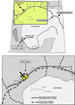
Lower Cretaceous carbonates are the most prolific reservoir facies in the Gulf of Mexico basin. Pro duction from these reservoirs extends along major portions of the basin from eastern Louisiana across southern Texas and including the vast reserves of east-central Mexico. To reassess the viability of the trend in the United States, Chevron geoscientists focused on an area in south Texas near the San Marcos arch (Figure 1). Through the detailed analysis of seismic, well information, and outcrops, we were able to develop a sequence stratigraphic framework for the Lower Cretaceous and to reinterpret shelf margin position and depositional history.
Exploration concepts focused on the Lower Cretaceous Edwards (Stuart City) and Sligo margins (Figure 1). Within the study area, the Edwards margin has been mapped in numerous publications as coincident with the Sligo margin (e.g., Meyerhoff, 1967; Fisher and Rodda, 1969; Bebout and Loucks, 1974); however, our work clearly demonstrates that the Edwards margin actually progrades seaward (southeastward) beyond the Sligo margin. This extension of the favorable stratigraphy of the Edwards beyond the commonly recognized margin presents abundant opportunities for future exploration in both the Edwards and Sligo. In particular, our work indicates that the Sligo is a well-defined aggradational margin that underwent a major period of exposure, resulting in deposition of a series of downslope debris wedges. Such wedges form the principal reservoirs in the prolific Golden Lane (Poza Rica trend) of eastern Mexico. These de posits have not been drilled in the United States to the best of our knowledge and present huge exploratory possibilities.
The study area is located in east-central Texas proximal to the San Marcos arch (Figure 1a). This area was chosen due to its structural potential for focusing hydrocarbons. Figure 1b shows that the margins of the Edwards and Sligo are coincident in a few areas but diverge quite often along the trend. Relevant Cretaceous stratigraphy in the study area is given in Figure 2.
A 2-D seismic structure map on the top of the Edwards (Figure 3) suggests that the Edwards and Sligo margins are stacked in this area. The presumed location of the overlapping margins is clearly depicted by apparent hinging in the structure map. By reviewing the seismic lines shown on the map, we demonstrate that what seems to be a definitive feature of the Edwards margin is, in fact, drape over the deeper Sligo margin; furthermore, faults and slight structures exist seaward of the apparent hinge zone and form the basis for significant downdip exploratory opportunities. The map of Figure 3 also indicates the location of the Word field, which will be discussed as a well-studied example of an Edwards play. Word field is a mature Edwards gas field producing at a depth of approximately 13,000 ft (3965 m). The significance of the field (cumulative production of 290 bcf, in-place reserves of 890 bcf) in defining plumbing mechanisms, porosity development, and trap style cannot be overstated.
Figure 4 is an interpreted 2-D seismic line (line A of Figure 3) demonstrating the architecture of the Cretaceous shelf and margin in the study area. We have defined nine sequences within the interval from the Cotton Valley Formation through the top of the Edwards. The sequence boundary at the top of our sequence 5 within the upper Sligo is equivalent to the 112 Ma sequence boundary of Goldhammer et al. (1991) and marks a key period of erosion and potential deposition of coarse debris downslope. The boundary between sequences 6 (uppermost Sligo) and 7 (Pearsall) is interpreted to be a drowning unconformity. The sequence 9 boundary at the top of the Edwards coincides with the 98 Ma sequence boundary of Goldhammer et al. (1991) and is interpreted to be a time of dissolution of coarse back-reef grainstones.
Note on Figure 4 that the aggradational nature of the Sligo margin produces a "false"margin in the overlying Edwards Formation. Close examination of the data reveals continued thickening of the Ed wards (sequence 9) seaward (southeastward) of the Sligo margin, indicating that the true Edwards margin lies off the right end of the seismic line. The flexure caused by the underlying Sligo margin creates a level of instability in the overlying sediments that leads to faulting and perhaps fracturing, as we demonstrate in following sections.
THE EDWARDS--AN UNDERDRILLED OPPORTUNITY
The depositional nature of the Edwards (Stuart City) margin has been examined by several workers, including Bebout and Loucks (1974) and Baker and Scott (1985). Figure 5 shows a cross section modified from Baker and Scott (1985) providing a conceptual framework for the Word field complex of grainstones. This, in turn, formed the basis for our pursuit of potential Edwards reservoir fairways downdip. Figure 5 indicates a carbonate reef and associated detritus in front of the island complex represented by Word field. Our study of well cuttings and core, coupled with detailed seismic correlation, confirms that the Edwards margin consists of both grainstone and reef facies, but led us to the conclusion that both sets of facies repeat themselves several times within the Edwards as the margin prograded. In essence, there are equivalent facies to those of Word field downdip of the field, but the facies lack the underpinning of the Sligo margin for structural drape. The stratigraphic context of the Edwards progradation was not captured in previous studies.
Figure 6 is a 3-D seismic line (line B of Figure 3) revealing more detail of the Edwards structure across and seaward of the Sligo margin. Word field lies directly above the Sligo margin, putting the Edwards in a structural position where it is cut by at least two faults. These data suggest that the Edwards in Word field is likely a fault-plumbed horizon. Elongate trends of porosity in the field that parallel depositional strike are indicated by log correlation, 3-D seismic acoustic impedance analysis, and well productivity maps (Baker and Scott, 1985; Weathers, 1996). Although the elongate nature of the porosity development is consistent with the geologic model of Baker and Scott (1985), postulating meteoric water-induced dissolution in a beach ridge setting, we believe that dissolution attributable to subsurface-derived fluids moving along faults is also important. The thickness of porosity zones (phi-H) in some wells suggests a dissolution mechanism that crosscuts stratigraphy, which we believe is not expected with the geologic model of Baker and Scott (1985). In addition, the nature of the porosity and pore-filling calcite cements observed in cores suggests burial diagenesis. We have observed vuggy and solution-enlarged fracture porosity, which does not disprove syndepositional meteoric dissolution, but is more likely a result of burial dissolution. We have also observed coarse, hydrocarbon-stained calcite cements locally filling the porosity; these cements are commonly observed products of burial cementation. We conclude that subsurface fluids moving along fault pathways are an important mechanism for porosity enhancement and hydrocarbon emplacement in Word field. The fact that grainstone-packstone facies are coincident with the faults is also critical to the production seen at Word field.
The extension of the Edwards seaward of Word field is a progradational belt that occurs toward the right on the seismic line of Figure 6. The structures outboard (southeast) of Word field are also plumbed by faults, as shown on Figure 6, and represent optimal targets for exploration. These structures are largely untested; however, note that the structural closure shown at the far right end of the seismic line has been tested by the General Crude 1 Bertha Anderson well and contains potentially commercial hydrocarbon reserves. The well has not yet been placed on production due to a significant amount of gas encountered in the shallower Wilcox interval.
Information from wells located seaward of the commonly recognized Edwards margin helps reveal the stratigraphic implications of the seismic data. Our analysis of sample descriptions from several wells drilled downdip from Word field indicates that shallow-water Edwards facies are present. Six wells contained miliolid foraminifers, rudist and other shell fragments, or traces of boundstone, suggesting that reef and back-reef environments were present. The Chevron 1 Coby well illustrates the relevant Edwards stratigraphy. The well location is shown on Figure 7, which also gives the outline of a 3-D seismic survey conducted immediately in front of the published Edwards margin. Interpreted log and drill-cutting information from the Chevron 1 Coby well is shown in Figure 8. Drill cuttings collected every 10 ft (3.05 m) were examined in thin section over the entire interval. The interpretation shows a progradational succession in the Edwards/Glen Rose from deep-shelf argillaceous wackestones up through back-reef grainstones. The depositional facies shown for the Coby well suggest that the Edwards reef margin prograded seaward even at this location.
A user track through the 3-D seismic volume (line C, Figure 3) and a corresponding geologic cross section show the progradational nature of the Edwards in more detail (Figures 9, 10). The user track is located specifically as shown on Figure 7 and includes three wells (Figure 9). The Mobil Kahenek 1 well (Bebout and Kupecz, 1985) is projected 13 mi (21 km) along depositional strike from Word field, whereas the Chevron 1 Coby and the Exxon 1 Joe Zaruba wells are on the user track (see Figure 7). The wells have been depth-tied to the seismic data on the basis of sonic or density logs and synthetic seismic traces. Four seismic reflectors, labeled reflectors 1-4 on Figure 9, are interpreted from stratal geometries to be sequence boundaries. The three Edwards sequences defined by the four boundaries occur within sequence 9 on the 2-D seismic of Figure 4.
The four key seismic reflectors within the Ed wards on Figure 9 were used to assist in correlating the wells on the cross section of Figure 10. Reflector 1 is a high-amplitude reflector downdip that diminishes in strength updip (Figure 9). This reflector occurs at the top of an interval of deeper water argillaceous wackestones (upper Tamaulipas) and is equivalent to the sequence boundary at the top of sequence 8 on Figure 4. Reflector 1 is immediately overlain by a prograding reef and bank complex of the Edwards margin seen in cores from the Kahanek well and distal slope wackestones de scribed from cuttings of the Coby well (Figure 10). Reflector 2 of Figure 9 is weak and ties the lagoonal packstone/grainstones in the Kahanek cores to a reef and bank complex in the Coby cuttings (Figure 10). We infer that this reflector ties to fore-reef and slope deposits in the Zaruba well.
Reflector 3 of Figure 9 ties back-reef wackestone/packstones of the Kahanek cores to reef and back-reef grainstones in the Coby cuttings (Figure 10). We interpret from the logs of the Zaruba well that a reef and minor fore-reef succession are present in this interval. Reflector 4 of Figure 9 ties back-reef deposits in the Kahanek well (inferred from logs and observed in the equivalent interval in other Word field cores) to back-reef packstone/ wackestones in cuttings from the Coby well. These same deposits are correlated to reef and back-reef grainstones seen in cores from the Zaruba well. Reflector 4 is equivalent to the sequence boundary at the top of sequence 9 on Figure 4 and to the 98 Ma sequence boundary of Goldhammer et al. (1991). It seems clear that even this "top Edwards" interval between reflectors 3 and 4 represents a progradational package whose ultimate culmination is seaward of the Zaruba well. The correlations shown on Figures 9 and 10 thus delineate prospective grainstone packages as much as 3 mi (4.8 km) or more seaward of the published Edwards margin.
The impact of these findings is considerable. Clearly defined is a virtually unprospected area of the Edwards with significant potential for new gas reserves. The highly progradational nature of the Edwards margin places prospective back-reef and reef grainstones far seaward of the recognized margin. Development of a high-resolution sequence stratigraphic framework reveals the location of favorable facies, as can be seen by comparing the 2-D seismic expression of Edwards sequence 9 on Figure 4 with the three Edwards sequences identified on the 3-D data of Figure 9. This information, coupled with the likelihood that faulting can create avenues for secondary porosity development in the Edwards and charge the system with hydrocarbons from deeper Tamaulipas source rocks, makes it evident that numerous opportunities for exploratory drilling exist. The extent of this opportunity fairway within Lavaca County alone is over 3 mi (4.8 km) in width and 25 mi (40 km) in length (Figure 11).
THE SLIGO FOREREEF--AN UNTESTED OPPORTUNITY
Our Cretaceous studies examined the prolific fields of east-central Mexico and found that the Poza Rica field (see Figure 1 for location) appeared to be an analog for a concept we had identified along the Sligo margin in Texas. Poza Rica is a giant offshore field in the Tampico embayment, producing from the Albian-Cenomanian Tamabra formation. The cross section of Figure 12 illustrates the depositional setting for the Poza Rica field. Fore-reef grainstones and packstones and intraclast breccia of partly shelf-derived skeletal material occur as a thick wedge trapped along the flank of the Golden Lane isolated platform (Enos, 1985). Note on Figure 12 that the downslope wedge is developed on both sides of the platform.
Figure 13 shows an outcrop photograph from northern Mexico where Goldhammer et al. (1991) identified a sequence boundary (the 112 Ma se quence boundary) within the upper Sligo equivalents of the Cupido and Cupidito formations. This boundary appears as the prominent notch in the center of the photograph at the skyline. The boundary marked a period of dissolution and erosion on the platform, and was a time, we suspect, that debris and grainstones were carried downslope in front of the margin. Any downslope relationships cannot be investigated on the outcrops due a lack of slope exposures.
The sequence boundary separating the Cupido from the overlying Cupidito can be carried into Texas. Using well control, the boundary can be tied to a potential hiatus on the margin, whereas seismic data identify the boundary with a clear disconformity along the margin front. The 3-D seismic line shown in Figure 14 (line B of Figure 3, as is Figure 6) points out this sequence boundary (shown in blue) in the Sligo margin. The same boundary is identified on the 3-D seismic line of Figure 9 and the 2-D seismic line of Figure 4 (sequence boundary at top of sequence 5). Figure 14 appears to indicate several events on the seaward side of the margin that display onlap and downlap reflector terminations. These events exhibit the proper architecture to comprise part of a downslope debris wedge in excess of 1000 ft (305 m) thick. The wedge sits adjacent to a steep shelf margin that has some similarity to the Capitan reef margin, for example, as revealed in outcrops at McKittrick Canyon in the Guadalupe Mountains of west Texas and New Mexico. The Sligo debris wedge on the 3-D seismic data of Figure 14 is also visible on the 2-D data of Figure 4 (downslope portion of our sequence 6).
The existence of a Sligo downslope wedge between the sequence boundary and the overlying Pearsall shale (shown in green on Figure 14) does not guarantee the presence of coarse-grained material, but it strongly implies it. In our interpretation, there were two primary sources of carbonate production during the sea level lowstand associated with the sequence boundary that would have supplied sediment to the wedge: (1) erosional retreat of the shelf margin and (2) in-place growth of reef-grainstone environments on the slope. We believe the lowstand created a period of instability, resulting in coarse breccia and grainstone transported farther downslope in the form of debris flows and sediment gravity flows, forming the debris wedge at the base of slope. During the subsequent transgression and relative highstand, the Sligo shelf margin kept up with sea level rise and continued to contribute grainstone debris downslope (also included within sequence 6 on Figure 4). This uppermost Sligo deposition corresponds to the Cupidito of the northern Mexico outcrops (Goldhammer et al., 1991). Rapid deposition of the downslope carbonates may have helped to preserve primary porosity by limiting the amount of marine cementation. Eventually, the Sligo shelf margin was flooded by the major transgression represented by the Pearsall, which would provide a hydrocarbon seal. Sequence 7 on Figure 4 is equivalent to the Pearsall formation; as has been previously mentioned, we interpret the sequence boundary between sequences 6 and 7 to be a drowning unconformity.
These conclusions are in contrast to those of Dravis and Wanless (1999) regarding the predicted regional distribution of Lower Cretaceous carbonate debris wedges. In their analysis of such deposits, these workers stressed the importance of strong winds in controlling the production of carbonate sands on top of the modern Caicos platform in the southeast Bahamas, as well as the transportation of these sands off the leeward margin of the platform. Using both the model derived from the Caicos and their observation that Poza Rica is a wedge of grainstones developed only on the western (leeward?) edge of the Golden Lane platform, Dravis and Wan less (1999) suggested that Lower Cretaceous debris wedges would more likely exist off the western sides of the Yucatan Peninsula and Florida escarpment and not off the windward margin in Texas. Three observations, however, are at odds with their reasoning and support the notion that the Sligo debris wedge of onshore Texas is a viable exploration target: (1) recent analysis of the Poza Rica trend, as illustrated in Figure 12 and in such studies as Enos (1985), shows that the downslope debris wedge is developed on both sides of the Golden Lane platform; (2) Enos (1985, 1986, 1988), among others, demonstrated that the Poza Rica wedge consists of coarse intraclast debris and not exclusively grainstones; and (3) studies from many modern carbonate areas show a coarse debris and grainstone apron downslope of windward reef margins.
We submit that the Caicos model, as discussed by Dravis and Wanless (1999), although potentially important for understanding offbank transport by wind-driven currents of carbonate muds and sands, does not explain the distribution or composition of the Poza Rica downslope wedge, nor does it lessen the exploration potential of the Sligo downslope wedge. This potential is represented by the stylized cross section of Figure 15 across the Sligo margin in south Texas. The cross section is based on seismic characteristics observed on the 3-D seismic lines of Figures 14 and 9, as well as other seismic data in the area. The risk elements of reservoir quality and trap are the most difficult to mitigate in this play, but the potential remains high. We believe the Poza Rica demonstrates that the correct combination of facies and diagenesis can occur to produce adequate reservoir quality (Enos, 1986, 1988). The Sligo wedge is of considerable scale, being over 1000 ft (305 m) in thickness and extending for several miles in a dip direction. Stratigraphic trapping is expected as a result of downslope facies variation across small-scale sequence boundaries, and slumping and faulting of the slope might produce fault traps. Fine-grained deposits of the Pearsall formation are a potential top seal.
The use of 3-D seismic is critical in defining and properly testing a target of this type. A few wells drilled in Louisiana, such as the Union 1 Kirby well (Tyrrell and Scott, 1989), may have penetrated the distal end of the Sligo debris wedge, but the debris wedge itself apparently has not been drilled. We believe the Sligo fore-reef and slope play is regional in extent throughout the northern rim of the Gulf of Mexico (Figure 16), and this play opportunity has yet to be tested.
The Lower Cretaceous of the Texas Gulf Coast remains an area with a high potential for significant reserves of oil and gas. The Edwards and Sligo plays presented in this study, as well as other Lower Cretaceous objectives, are far from fully exploited and make attractive targets for future exploration. Plays and prospects can be identified by using a combination of high-resolution 3-D seismic data, carbonate sequence stratigraphic concepts, and core and cutting descriptions. These results, coupled with the realization that faults are key pathways for secondary porosity and migration of hydrocarbons, improve the chances for a discovery.
Baker, H. W., and E. Scott, 1985, Intermittent subaerial exposure responsible for porosity development in Edwards limestone, Lavaca County, Texas, in D. G. Bebout and D. Ratcliff, eds., Lower Cretaceous depositional environments from shoreline to slope--a core workshop: Austin, Gulf Coast Association Geological Societies Annual Meeting, p. 31-35.
Bebout, D. G., and J. A. Kupecz, 1985, Lower Cretaceous Stuart City trend facies and environments, Mobil No. 1 Kahanek core, Lavaca County, Texas, in D. G. Bebout and D. Ratcliff, eds., Lower Cretaceous depositional environments from shoreline to slope--a core workshop: Austin, Gulf Coast Association Geological Societies Annual Meeting, p. 55-63.
Bebout, D. G., and R. G. Loucks, 1974, Stuart City trend, Lower Cretaceous, south Texas--a carbonate shelf-margin model for hydrocarbon exploration: University of Texas, Bureau of Economic Geology, Report of Investigations 78, 80 p.
Dravis, J. J., and H. R. Wanless, 1999, Application of the Caicos platform model to exploration: trade wind controls on carbonate play distribution: AAPG Annual Convention Program and Abstracts, p. A34.
Enos, P., 1985, Cretaceous debris reservoirs, Poza Rica field, Veracruz, Mexico, in P. O. Roehl and P. W. Choquette, eds., Carbonate petroleum reservoirs: New York, Springer-Verlag, p. 457-469.
Enos, P., 1986, Diagenesis of mid-Cretaceous rudist banks, Valles platform, Mexico, in J. H. Schroeder and B. H. Purser, eds., Reef diagenesis: Berlin, Springer-Verlag, p. 160-185.
Enos, P., 1988, Evolution of pore space in the Poza Rica trend (mid-Cretaceous), Mexico: Sedimentology, v. 35, p. 287-325.
Fisher, W. L., and P. U. Rodda, 1969, Edwards Formation (Lower Cretaceous), Texas--dolomitization in a carbonate platform system: AAPG Bulletin, v. 53, p. 55-72.
Goldhammer, R. K., P. J. Lehmann, R. G. Todd, J. L. Wilson, W. C. Ward, and C. R. Johnson, 1991, Sequence stratigraphy and cyclostratigraphy of the Mesozoic of the Sierra Madre Oriental, northeast Mexico: Houston, Gulf Coast Section SEPM Foundation, Field Trip Guidebook, 86 p.
Meyerhoff, A. A., 1967, Future hydrocarbon provinces of Gulf of Mexico-Caribbean region: Trans., Gulf Coast Association Geological Societies, v. 17, p. 217-260.
Tyrrell, W. W., Jr. and R. W. Scott, 1989, Early Cretaceous shelf margins, Vernon Parish, Louisiana, in A. W. Bally, ed., Atlas of seismic stratigraphy: AAPG Studies in Geology 27, v. 3, p. 11-17.
Weathers, L. R., 1996, Reservoir description using acoustic impedance--Halletsville 3-D: Society of Exploration Geophysicists, Annual Meeting Expanded Abstracts, p. 762-765.
Yurewicz, D. A., R. J. Chuchla, M. Richardson, R. J. Pottorf, G. G. Gray, M. G. Kozar, and W. M. Fitchen, 1997, Hydrocarbon generation and migration in the Tampico-Mislanta basin and Sierra Madre Oriental, east-central Mexico: evidence from an exhumed oil field in the Sierra de el Abra, in P. Enos, C. J. Minero, R. R. Aracen, and D. A. Yurewicz, eds., Sedimentation and diagenesis of Middle Cretaceous platform margins, east central Mexico: Dallas, Dallas Geological Society and SEPM Field Trip Guidebook 4, p. 1-24.
Dale A. Fritz
Dale Fritz is a senior staff earth scientist in the Gulf Division of Santa Fe Snyder Corporation of Houston, Texas. His petroleum career has included working for Chevron for 17 years. He joined Chevron after receiving a B.S. degree in geology and an M.S. degree in geology from the University of Wisconsin-Milwaukee in 1980 and 1982, respectively. During his exploration career with Chevron, he spent 10 years working the offshore Gulf of Mexico, several years on the Exploration VP's staff, and the last 5 years working onshore plays in Texas. He recently accepted a position with the Santa Fe Snyder Corporation. He is keenly interested in the pursuit and development of high NPV prospects from concept through production.
Terry W. Belsher
Terry W. Belsher is a senior geologist in the Mid continent Business Unit of Chevron U.S.A. Production Company in Houston, Texas. He joined Chevron in 1980 after receiving a B.S. degree in geology from Stephen F. Austin State University. His assignments have included exploration and development projects focused on carbonate reservoirs of the Ordovician-Permian in the Permian basin, and the Jurassic and Cretaceous of the Texas and Mississippi Gulf Coast regions.
James M. Medlin
James M. Medlin recently retired as a senior staff geophysicist in the Midcontinent Business Unit of Chevron U.S.A. Production Company in Houston, Texas. He joined Gulf Oil after receiving a B.S. degree in geology, geophysics option, from the University of Missouri at Rolla in 1967. During his exploration career with Gulf, he spent 3 years in Venezuela, followed by exploration and research assignments in various U.S. locations. Jim joined Chevron in 1985 and has worked with groups exploring in several Gulf coast, mid-continent, and Rocky Mountain basins. His main interests are integrating seismic interpretations into high-impact exploration plays and extracting both chronostratigraphic and lithostratigraphic information from the seismic signal.
John L. Stubbs
John L. Stubbs, Jr., received his B.S. degree in geology from West Virginia University (1975) and his M.S. degree in geology from Virginia Polytechnic Institute (1977). He joined Chevron in 1977 in New Orleans working ex ploration and development assignments in the onshore and offshore Gulf of Mexico region, Appalachian basin, Illinois basin, and Black Warrior basin. Currently, he is working as an earth scientist for the south Texas area for the Midcontinent Business Unit of Chevron U.S.A. Production Company in Houston, Texas.
Robert P. Wright
Robert Wright is a staff geologist for the Midcontinent Business Unit of Chevron U.S.A. Production Company in Houston, Texas. His work in sequence stratigraphy is primarily in Alaska and the U.S. Gulf Coast. Before working for Chevron, he was senior geologist at the Cities Service Research Laboratory in Tulsa, Oklahoma, with projects worldwide. He received a B.A. degree (1965) in geology from the University of Connecticut and an M.S. degree (1967) and Ph.D. (1970) from the University of Michigan. Robert's main interest is to integrate outcrop, subsurface, and seismic data to predict reservoir occurrence.
Paul M. (Mitch) Harris
Mitch Harris is a senior staff research geologist with Chevron Petroleum Technology Company in Houston, Texas. He provides carbonate technical support projects, consulting, and training for the various operating units of Chevron. His work during the last 22 years has centered on facies-related, stratigraphic, and diagenetic problems that pertain to carbonate reservoirs and exploration plays in most carbonate basins worldwide. Mitch received his B.S. and M.S. degrees from West Virginia University and his Ph.D. from the University of Miami, Florida. He has published numerous papers, edited several books, and is active in AAPG and SEPM.
We thank our coworkers for support in various stages of our studies. Scott Butler was a strong source of support for the work done on this project, and we are all indebted to him for his perseverance with management to allow these concepts to be developed and pursued. Glenn Priess helped acquire data and Juan Narbona drafted the figures. We would like to acknowledge John Sangree for his initial overview, encouragement to pursue a deep Cretaceous play, and early recognition of the key sequence boundary in the Sligo. We are also indebted to Brad Macurda, Bob Goldhammer, and Clyde Moore for their insights on the Lower Cretaceous of the Gulf Coast. Seismic data are credited to Seismic Exchange, Inc., and CGG American Services. Chevron granted permission to publish the manuscript. Comments by AAPG reviewers Scott Montgomery, Neil Hurley, and Lee Billingsley improved the manuscript greatly.