![]() Click to view article in PDF format.
Click to view article in PDF format.
Results and Conclusions of a Horizontal-drilling Program at South Pass 62 Salt-dome Field*
By
E.P. Mason1, M.J. Bastian1, R. Detomo1, M.N. Hashem1, and A.J. Hildebrandt1
Search and Discovery Article #20018 (2004)
*Adaptation for online presentation of the article with the same title by the same authors in AAPG Methods in Exploration No. 14, entitled Horizontal Wells: Focus on the Reservoir, edited by T.R. Carr, E.P. Mason, and C.T. Feazel. This volume is available from AAPG’s Online Bookstore (http://bookstore.aapg.org).
1Shell Exploration & Production Company, New Orleans, Louisiana, U.S.A. ([email protected]).
A horizontal-well redevelopment drilling program around the flanks of the South Pass 62 salt-dome field resulted in significant successes and costly failures. Successful wells exploited thin, oil-filled shoreface sandstones; partially depleted zones; and massive, sand-filled channels. Failures were those wells that attempted to connect multiple fault blocks and drain low-resistivity/laminated-sandstone reservoirs. This paper reviews the field history; describes the geologic setting, including a summary of significant structural features and producing-sandstone depositional environments; discusses the horizontal- well strategy; and examines successful and unsuccessful wells.
South Pass 62 field lies 50 km (30 mi) east of the Mississippi River delta in 104 m (300 ft) of water. The field was discovered in 1965, developed with 61 directionally drilled wells from three platforms in the late 1960s, redeveloped from 1986 to 1988 with 31 wells from a fourth platform, and redeveloped again from 1994 to the present with horizontal and directionally drilled slim-hole sidetracks. A 3-D seismic-based field study completed in 1994 identified reservoir targets for the horizontal-drilling program.
Nearly 60 stacked, variable pay sandstones combine with steep formation dips and extensive faulting to create a complex field with hundreds of reservoirs. The field lies on the north flank of a mushroom-shaped, south-leaning salt dome that rises from below 8000 m (25,000 ft) to within 200 m (656 ft) of the seafloor. Typical formation structural dips decrease from 70° adjacent to the salt to 10° off structure. Several generations of faults exist, with throws ranging from centimeters to more than 100 m. Approximately 60 Pliocene and Miocene deltaic and turbidite pay sandstones ranging in depth from 1158 to 5791 m (3800 to 19,000 ft) onlap the salt.
|
uD34 (faulted channel sandstone)
uD34 (faulted channel sandstone)
uD34 (faulted channel sandstone)
uD34 (faulted channel sandstone)
uD34 (faulted channel sandstone)
uD34 (faulted channel sandstone)
uD34 (faulted channel sandstone)
uD34 (faulted channel sandstone)
uD34 (faulted channel sandstone)
uD34 (faulted channel sandstone)
uD34 (faulted channel sandstone)
|
Between 1994 and 1997, Shell Exploration & Production Company redeveloped South Pass 62 field (SP62) in the Gulf of Mexico in an attempt to restore the aging giant’s profitability. Daily production had declined from 30,000 bbl of oil to 2000 bbl, and operating costs had soared. Although large volumes of oil and gas remained in the field, most were producible only through low-rate, conventional, gravel-pack recompletions of partly depleted zones and thin, laminated sandstones. Nearly 200 faults dissecting 60 pay sandstones created hundreds of reservoirs in the field. Thirty years of production had resulted in many depleted reservoirs and many others in various stages of depletion. Many small, unpenetrated fault blocks with reserves too low to justify a well also existed. These conditions made SP62 an extraordinarily complicated field and difficult to redevelop profitably. Horizontal wells appeared to be the solution.
Horizontal Drilling in the Gulf of Mexico By 1990, horizontal wells had become commonplace nearly everywhere except in the Gulf of Mexico. The benefits of recovery and rate in unconsolidated sandstones were thought to be small, although dramatic improvements had been observed in similar environments elsewhere (Stark, 1992). Texaco U.S.A. initiated horizontal drilling in the Gulf of Mexico when it spudded well B-12 in East Cameron Block 278 in May, 1990 (Fisher and French, 1991; Cochrane and Reynolds, 1992). This well was drilled successfully to deplete a gas sandstone 442 m below the mud line; it proved that horizontal wells were a viable alternative to extended-reach development wells. The company followed up with horizontal wells in other fields. At South Marsh Island 239, a horizontal well was drilled to a then record true vertical depth of 3076 m (Jenkins and Patrickis, 1992). At the “Teal” Prospect (Eugene Island 338), a horizontal well was drilled to improve recovery from a depleted oil reservoir (World Oil, 1992). At Eugene Island Block 228, a 431-m lateral section was drilled and completed (Pardo and Patrickis, 1992). Other operators, large and small, also began to have success with horizontal wells in the Gulf of Mexico. In 1992, Chevron U.S.A., Inc., experienced a sixfold increase in production rates from three horizontal wells drilled in shallow, Pleistocene gas sandstones at two fields (Gidman et al, 1995). Kerr-McGee Corp. exploited a thin oil column, reducing the effect of coning and realizing an eightfold increase in initial rates at Breton Sound Block 20 field, also in 1992 (Paull, 1993). In 1993, Pogo Producing Company completed a five-well horizontal program at Eugene Island Block 295 “B” in zones that would have been uneconomical to develop with vertical or directional wells. Combined rates reached 101 MMCFGD (Schroeder et al., 1995). Amoco successfully redeveloped thin oil reservoirs with a four-well horizontal-drilling program in bottom-water-drive reservoirs with 7-m oil columns. Reentry sidetracks were also being attempted successfully, including Shell’s first horizontal wells in the Gulf of Mexico. At Mississippi Canyon 194 field (“Cognac”) in 1994, oil rims 18 to 30 m thick were successfully exploited using slim-hole sidetracks. Productivity improvements of three to ten times were observed (Danahy and Scheibal, 1997). These very profitable sidetracks were drilled with workover-class platform rigs to accelerate recovery of oil reserves prior to gas-cap blowdown. They opened up a new avenue for increasing production rates at many of Shell’s older, declining fields on the Gulf of Mexico shelf. More recently, Exxon Company U.S.A. has applied this same strategy in redeveloping mature fields in the Gulf of Mexico (Batchelor and Moyer, 1997). At South Pass 62, we decided to apply this “new” technology for Shell in the Gulf of Mexico to redevelop the field. Ultimately, nine horizontal sidetracks, two new horizontal wells, and five directional sidetracks were drilled at SP62. Production rates increased dramatically, peaking at 15,000 BOPD, largely because of the productivity improvement from the horizontal wells. However, the phenomenal successes were tempered by several costly failures. This paper describes the types of horizontal wells drilled, examines the successes and failures, and summarizes the conclusions and best practices.
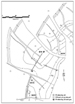
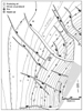
South Pass 62 field, lying 50 km southeast of the Mississippi River delta in 100 m of water (Figure 1), was discovered in 1965. It was developed with 61 directionally drilled wells from three platforms in the late 1960s, redeveloped from 1986 to 1988 with 31 wells from a fourth platform, and redeveloped again from 1994 to 1997 with horizontal and directionally drilled slim-hole sidetracks (Figures 2 and 3). A 3-D seismic-based field study completed in 1994 identified reservoir targets for the horizontal- drilling program. Cumulative production from block 62 is 108 MMBO and 170 BCFG. Peak daily production rates reached 30,000 bbl and 50 MMCFG in 1970 before declining to 2000 bbl in 1994
SP62 field lies on the south rim of a large, salt-withdrawal minibasin (Cheetah minibasin, Figure 1). The south rim is defined by a large, pressure-changing, northdipping, counterregional fault. The north flank is defined by a series of arcuate, regional, south-dipping faults. Basin formation began in the early Miocene in response to sediment loading. As the ancestral Mississippi River deposited sediment in the north, mobile salt was forced southward into a salt ridge. This ridge provided a backstop for lower Miocene turbidites cascading down the continental slope. Continued deposition resulted in further loading, continued salt-ridge growth, and eventual rupture of the overlying Eocene chalk along the ridge crest. Salt, squeezed out of the ridge, localized into a dome at SP62. The Cheetah minibasin is extraordinarily rich; almost every closure within the basin contains oil.
Salt and salt-related faulting dominate the structure and form the trap at South Pass 62 field. Salt rises from a depth of approximately 8000 m through Eocene chalk and Miocene, Pliocene, and Pleistocene clastics to within 200 m of the seafloor (Figure 4). The salt body leans to the south and is mushroom shaped, with a thin root and massive head. The north face is concave, sculpted by a north-dipping arcuate slump. Numerous thin salt lenses as much as several hundred meters thick are found on the west flank of the dome. These lenses are defined by well penetrations but are unseen on 3-D seismic data. Formation structure is characterized by dips in excess of 70° adjacent to the salt, and decreasing to less than 10° away from the structure (Figure 5). Faults are prevalent at SP62. Approximately 200 seismically resolvable faults with throws ranging from five to hundreds of meters dissect and compartmentalize the producing horizons. The field is separated into four megacompartments by three major faults: (1) a large, counterregional fault/salt evacuation surface separating the productive north flank from the nonproductive south flank; (2) an arcuate slump defining the north salt face; and (3) a fault system antithetic to the slump. These faults have always been barriers to flow, despite sandstone-on-sandstone juxtaposition across each respective fault. The mushroom-shaped salt overhang provides an excellent trap at SP62. Hydrocarbon column heights in excess of 900 m are common.
Stratigraphy and Depositional Environment Approximately 60 Piocene and Miocene deltaic and turbidite pay sandstones range in depth from 1000 to 6000 m. Horizontal wells focused on seven upper Miocene deltaic and shoreface sandstones (Figure 6). Typically, these sandstones were fine grained, well sorted, uncemented, and normally pressured. Upper-shoreface sandstones (e.g., M4) typically were 3 to 6 m thick, continuous, upward coarsening, well connected, and easy to correlate. Horizontal wells in these reservoirs were the program’s most productive and profitable (C11 and D32). Excellent connectivity and continuity resulted in high rates and good drainage. Lower-shoreface intervals were characterized by thin beds, low resistivity, and high continuity (N9 and U-U1). These zones consisted of 30- to 90-m bundles of centimeter- to meter-thick sandstone members. Individual sandstone members were difficult to correlate, but the gross intervals were not. Historically, at SP62, these intervals had produced small volumes at low rates using conventional gravel packs. Laterals drilled through lower-shoreface deposits were disappointing in that they sanded up after producing small amounts of oil. The use of preperforated screens might have alleviated this problem. Distributary channels, typified by the L10, M8, and V series, were characterized by rapid changes in thickness, variable connectivity and water contacts, and inconsistent drainage. Thicknesses ranged from a few meters to more than 30 m. Channel geometries and drainage were difficult to predict, despite integration of all well, production, and seismic data. In nearly every well penetrating channelized reservoirs, sandstone thickness and hydrocarbon distribution were significantly different than predicted. Laterals placed in channelized intervals yielded both extremely profitable and productive wells (C20st, A8st), as well as the most costly failure (D34). One horizontal well was drilled into the M sandstone, an incised valley deposit. The M sandstone is a massive, high-net/gross-ratio interval characterized by extreme variations in thickness. Thicknesses occasionally exceed 100 m. On gamma-ray logs, the M is blocky, with a sharp base and top. On seismic data and in cross section, the base cuts through different stratigraphic intervals, characteristic of an incised valley. The M sandstone exhibited excellent connectivity and productivity, and it produced with a strong water drive. Reservoir drive mechanisms varied from strong water drive to pure depletion drive. Thick, higher net/gross sandstones (M and M8) exhibited strong water drives where sandstone-on-sandstone juxtaposition across faults combined with exceptionally good stratigraphic connectivity to allow communication with downdip aquifers. The strong water drive seen in the M4 upper-shoreface deposit is attributed to excellent continuity and connectivity. With few exceptions, reservoirs adjacent to or near the salt face were depletion, or partial, water drive. Increased faulting and more variable stratigraphy combined to create small compartments disconnected from downdip aquifers. Deeper reservoirs also tended to be depletion drive.
SP62 was one of Shell’s first horizontal programs in the Gulf of Mexico; therefore, the company wanted not only to increase daily production and recover oil from low-rate/low-profitability reservoirs, but also to experiment with designs and try new concepts. Very little had been published in 1994 on horizontal-well applications in the Gulf of Mexico, and very few wells had been drilled. Successful techniques from SP62 could therefore be used in other fields. The strategy was to test play concepts on early wells, then prosecute the more successful plays with later wells, use slim-hole sidetracks (4 3/4-in. holes) from shut-in or temporarily abandoned wellbores as a low-cost alternative to new holes, and leverage service-company expertise in drilling horizontal wells.
Plays prosecuted at SP62 included using horizontal wells to drain underpressured reservoirs (two wells) and laminated/thin-bedded intervals (two wells), to connect multiple fault blocks with a single lateral (two wells), and to eliminate multiple recompletions and accelerate production (five wells). Frequently, several plays were tested with the same well. For example, well C17st connected three partly depleted fault blocks in a laminated/thinbedded sandstone interval. The most successful application at SP62 was the use of horizontal wells to eliminate recompletions in multiple wells and accelerate production, and to drain depleted sandstones.
Slim-hole sidetracks were seen as a low-cost alternative to drilling new wells at SP62. Many old boreholes were temporarily abandoned and ready to be recompleted or sidetracked. A typical procedure was to mill a window through 7 5/8-in. casing, drill a 6 1/2-in. medium- or long-radius build section into the top of the objective sandstone, and then set a 5 1/2-in. liner. A 4 3/4-in. lateral section followed; 3 3/8-in. wire-wrapped, prepacked screen was then run to total depth (TD). An oil-based mud system was used on most wells. Initial attempts using a salt-water-based mud system resulted in frequent and expensive hole problems.
The expertise of contracting companies Baker Hughes and Halliburton in drilling horizontal wells was used to the maximum extent possible in designing the horizontal program. Shell provided all available data to both companies and asked them to design the most efficient sidetracks. We provided target x and y coordinates and depths for the lateral section, directional data for all 130 wells from the four platforms, and mechanical sketches of all boreholes available for sidetrack. Both companies then developed a drilling program. We believe this resulted ultimately in a better-designed program and reduced cycle time, because Shell had insufficient drilling staff available to design this program.
Of the 11 horizontal wells drilled, five (D32st, C11st, A8st, C15st, and C20st) were very profitable, two (C17st, D36) generated a small profit, and four (D34, A18st, A4st, C19st) were commercial failures (Table 1). Well D32st far exceeded expectations and more than compensated for the unprofitable wells. Failures resulted either from mechanical failure, large cost overruns in drilling the well, or geologic “surprises” (e.g., undetected faults, perched water, unexpectedly low pressure). The two most successful wells and two significant failures are discussed in detail to highlight some of the most important information gleaned from this program.
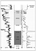
D32st (M4 Thin Shoreface Sandstone) Well D32st was drilled to accelerate production and improve drainage from a large, unproduced M4 sandstone reservoir. Several directionally drilled wells that had penetrated the reservoir were to be recompleted eventually in the M4 sandstone. Well D32st effectively drained much of the reservoir, making recompletions in several nearby directionally drilled wells unecessary. In the reservoir traversed by D32st, the M4 shoreface sandstone averaged 5-m gross (4-m net) thickness, coarsened upward with a sharp upper contact, and was highly continuous (Figures 7 and 8). The sandstone pinched out updip toward the salt. The structural dip of the M4 reservoir averaged 15° (Figure 9). Well D32st was drilled along structural strike, traversing the fault block downdip of the salt face. Lateral length was 761 m, of which 427 m consisted of clean sandstone (Figure 10). Well D32st has produced nearly 940,000 bbl of oil with a peak daily rate of 3400 bbl of oil, nearly 10 times that for conventional M4 completions (Figure 11). Similar success was achieved with the C11st horizontal well completed in the M4 sandstone in an adjacent fault block.
C20st (L10 Partially Depleted Distributary Channel Sandstone) C20st, the field’s first horizontal sidetrack, was drilled to improve recovery and accelerate production from a partially depleted L10 reservoir. By recovering M4 reserves that would have had to be recovered by recompleting nearby wells, those recompletions became unnecessary. The L10 consists of variable, channelized sandstones exhibiting sharp upper and lower contacts on well logs (Figure 12). In the objective fault blocks, the L10 was nearly 30 m thick. Well C20st was drilled along structural strike, crossing a fault thought to separate two L10 reservoirs (Figures 13, 14, and 15). Substantial production from downdip wells had depleted the reservoirs from initial pressures of 15,859 to 11,032 kPa (2300 to 1600 psi), as determined by Repeat Formation Tester (RFT) pressure measurements taken in the pilot hole and bottom-hole pressures taken in nearby wells. Because adjacent fault blocks exhibited similar bottom-hole pressures, we believed the fault blocks to be in communication through the downdip acquifer, if not across the faults. A 535-m, 4 3/4-in. lateral was drilled. While running the completion assembly into the borehole, the prepacked screen became stuck at about 275 m into the lateral section, leaving the last 260 m unscreened (Figure 16). Well C20st has produced 600,000 bbl of oil with peak daily rates exceeding 2200 bbl of oil, far surpassing expectations (Figure 17). Rate and pressure increases in 1998 and 1999 indicated that either additional sandstone stringers had begun to produce or that the last 260 m of the borehole had begun to contribute production.
C19st (N9 Lower-Shoreface Laminated Sandstone) Well C19st was drilled to recover reserves from a low-resistivity/ laminated-sandstone reservoir (Figures 18 and 19). The N9N10 zone consisted of a 37-m gross (12-m net) sandstone package over a large fault block. Numerous N9N10 penetrations existed that could have been recompleted as conventional gravel packs, but unfortunately, these completions produced at noncommercial rates. Peak rates from conventional completions reached only about 200 BOPD. We had hoped for rates of as much as 1500 BOPD. Well C19st was drilled across structure, so that the front of the lateral cut the interval from top to bottom, and the end of the lateral cut the interval from bottom to top (Figure 20). We at Shell believed that better drainage and higher rates would result. Particular care was taken in steering the lateral section so that the overlying, wet, N6N8 sandstone was not penetrated at the end of the lateral section. We had hoped that production rates and cumulative volumes produced would be large enough to make horizontal wells profitable in laminated sandstones across the field. Well C19st produced 170 MBO before sanding up after nine months of production. Initial peak rates reached 1900 BOPD, surpassing expectations (Figure 21). However, from the beginning of production, water was produced along with the oil, leading us to believe that communication between the lateral and the overlying N6N8 sandstone existed. Coiled tubing was used to wash sandstone from the lateral, but the well quickly sanded up again. Further workovers were deemed unlikely to bring the N9N10 lateral section back on production; therefore, the horizontal section was abandoned, and C19st was completed to another sandstone uphole. Preferential high-velocity fluid flow through more permeable sandstone laminae is thought to have eroded the screen at those points, allowing sandstone into the borehole. Failures in laminated sandstones at SP62 and other Shell fields were borne out in the laboratory (Fair et al., 1996). Other operators were experiencing similar screen failures (Pardo and Patrickis, 1992; Perdue, 1996; Foster et al., 1999). This convinced Shell to try “Frac’n’Pac” completions, which yielded high production rates without mechanical failures. They rapidly became the completion method of choice at SP62.
D-34 (L10 Distributary Channel Sandstone Connecting Multiple Fault Blocks) Well D34 was drilled to recover attic reserves in the L10 sandstone. The lateral was intended to connect three separate fault blocks and drain oil updip of producing wells (Figures 22 and 23). A pilot hole drilled near the front of the lateral section indicated well-developed oil-bearing sandstones (Figure 24) at close to original pressure. The lateral section was drilled successfully (after one sidetrack) and completed with two tubing strings (Figure 25). A short tubing string was set in the front of the lateral, and a long tubing string was set at the end of the lateral to allow production from separate fault blocks. The well began to produce at high rates, but pressures and rates declined quickly from the short string after only 35 MBO had been produced. In addition, the long string sanded up, nullifying the dual-completion concept. The well was worked over but could not be brought back on production. Well D34 was later sidetracked when it encountered the L10 sandstone at unexpectedly low pressure. It was subsequently recompleted in a sandstone farther uphole. Subsequent seismic reprocessing and reinterpretation revealed additional faults not recognized on the original 3-D seismic data set. These faults compartmentalized the reservoir much more than expected. In retrospect, it is clear that our original well plan had no chance of success. Well D34 was the most expensive failure in the drilling program. We conclude that we attempted too much with one borehole in an area where the geology was more complicated than we had realized.
Conclusions derived from this drilling program include: 1) The most successful horizontal wells were drilled in thin, shoreface sandstones (M4 sandstone) and massive channels (M and M8 sandstones) that had extraordinarily good continuity and connectivity. 2) Horizontal wells drilled in/through nested channels (L10) and laminated lower-shoreface deposits (N9N10 sandstone) were generally unsuccessful. Nested channels with perched water, variable water contacts, and unpredictable connectivity and continuity—typical of the L10 sandstone where well D34 was drilled—were disappointing and unprofitable. Laminated, thin-bedded intervals frequently resulted in early screen failure, which we attributed to screen erosion at the points of preferential/concentrated production in the cleanest, most permeable zones. 3) Risk of reservoir compartmentalization increased adjacent to the salt structure because the degree of faulting increased with proximity to the salt face. Wells A18st, D34, and D36 were drilled near the salt, and all encountered small compartments attributed to faulting. At SP62, laterals placed in massive, high net/gross, well-connected sandstones (e.g., M sandstone) had the highest probability of success adjacent to salt because connection to downdip aquifers and production across faults was more likely. 4) At South Pass 62, downdip reservoirs were preferred, primarily because unseen structural complexity was less likely. These sandstones also tended to be more continuous and connected. 5) Connecting multiple, small-fault blocks was costly. Lateral sections were more likely to collapse at faults, increasing well costs and decreasing profitability. 6) Simple, short well paths less than 450 m long that cut across or through the zone of interest were preferred. These boreholes provided a large increase in rates over vertical wells, without the high cost and drilling problems that accompanied nearly every long lateral drilled at SP62. 7) Low-pressure/depleted zones performed well. Three wells drilled through depleted reservoirs all produced at higher rates and for greater lengths of time than expected. 8) Prepacked, wire-wrapped screens frequently sanded up. Today we would use perforated screens. 9) The increased cost of pilot holes was more than offset by the value of knowledge gained from them. Pilot holes provide reservoir pressure information and a preview of the geology to be encountered at the start of the lateral section. This is critical information in a field with complicated geology and extensive production history.
The authors would like to thank Shell Exploration & Production Company for permission to publish and Tom Wilson and Vu Cung for their constructive comments.
Batchelor, B.J., and M.C. Moyer, 1997, Selection and drilling of recent Gulf of Mexico horizontal wells: Proceedings, 29th Offshore Technology Conference, Houston, Texas, OTC-8462, v. 3, p. 235–245. Cochrane, J.F., and K.C. Reynolds, 1992, Pressure transient analysis of a shallow horizontal gas well: Test objectives, design, procedure, interpretation, and application of results: Proceedings, Society of Petroleum Engineers, European Petroleum Conference, Cannes, France, SPE-25052, v. 2, p. 349–361. Danahy, M.A., and J.R. Scheibal, 1997, Exploitation of thin oil rims using horizontal sidetracks at Mississippi Canyon 194 (Cognac) Field (abs.): Annual AAPG Convention, Dallas, Texas. Fair, P.S., J. Kikani, C.D. White, 1996, Modeling high angle wells in laminated pay reservoirs: Proceedings, Annual Society of Petroleum Engineers Conference, Denver, Colorado, SPE-36027, p. 19–28. Fisher, E.K., and M.R. French, 1991, Drilling the first horizontal well in the Gulf of Mexico: A case history of East Cameron Block 278, well B-12: Proceedings, 66th Annual Society of Petroleum Engineers Technical Conference, Dallas, Texas, SPE-22545, p. 111–123. Foster, J., T. Grigsby, and J. Lafontaine, 1999, The evolution of horizontal completion techniques for the Gulf of Mexico: Where have we been and where are we going?: Proceedings, Sixth Society of Petroleum Engineers/Latin American and Caribbean Petroleum Engineering Conference, Caracas, Venezuela, SPE-53926, 15 p. Gidman, B., L.R. Hammons, and M.D. Paulk, 1995, Horizontal wells enhance development of thin offshore gas reservoirs: Petroleum Engineer, v. 67, no. 3, p. 19, 22–24. Jenkins, R.W., and A.N. Patrickis, 1992, Drilling the deepest horizontal well in the Gulf of Mexico, South Marsh Island 239 D-10: Proceedings, International Association of Drilling Contractors/Society of Petroleum Engineers Drilling Conference, New Orleans, Louisiana, IADC/SPE-23897, p. 317–329. Pardo, C.W., and A.N. Patrickis, 1992, Completion techniques used in horizontal wells drilled in shallow gas sandstones in the Gulf of Mexico: Proceedings, 67th Annual Society of Petroleum Engineers Conference, Washington, D.C., SPE-24842, p. 797–804. Paull, B.M., 1993, Horizontal well boosts mature Gulf of Mexico reservoir: Petroleum Engineering International, v. 65, no. 11, p. 16–19. Perdue, J.M., 1996, Completion experts study Gulf of Mexico horizontal screen failures: Petroleum Engineering International, v. 69, p. 31–33. Schroeder, T., D. Mathis, R. Howard, G. Williams, and J. Sun, 1995, Teamwork and geosteering pay off in horizontal project: Oil & Gas Journal, v. 93, p. 33–39. Schroeder, T., D.E. Mathis, A. Mathis, W.A. Hill, A. Ellis, and R.G. Hea, 1996, Various techniques optimize horizontal, shallow gas well, synopsis of SPE Paper 36489, scheduled for presentation at the SPE Annual Technical Conference and Exhibition, Denver, Colorado, October 6–9, 1996: Journal of Petroleum Technology, v. 48, no. 8, p. 734–737. Stark, P.H., 1992, Perspectives on horizontal drilling in western North America, in Geological studies relevant to horizontal drilling: Examples from western North America: Rocky Mountain Association of Geologists, p. 3–14. World Oil, 1992, Texaco isolates gas cap at Eugene Island: Gulf Coast Oil World, v. 12, no. 6, p. 25–27. |


