![]() Click to view 1st poster in PDF format.
Click to view 1st poster in PDF format.
![]() Click to view 2nd poster in PDF format.
Click to view 2nd poster in PDF format.
![]() Click to view 3rd poster in PDF format.
Click to view 3rd poster in PDF format.
Users may experience significant delays in downloading files due to their sizes.
PSSuccess! Using Seismic Attributes and Horizontal Drilling to Delineate and Exploit a Diagenetic Trap, Monterey Shale, San Joaquin Valley, California*
By
Anne Grau1, Robert Sterling1, and Robert Kidney1
Search and Discovery Article #20011 (2003)
*Adapted for online presentation from poster presented at AAPG’s annual convention, 2003, Salt Lake City, May, 2003. A companion article, entitled “Delineation of a Diagenetic Trap Using P-Wave and Converted-Wave Seismic Data in the Miocene McLure Shale, San Joaquin Basin, California,” is Search and Discovery Article #20012 (2003).
1EOG Resources, Denver Colorado (anne [email protected])
The Miocene Monterey Formation of California’s San Joaquin valley has long been recognized as a prolific source rock and underdeveloped resource. In this case study, the thick sequence of diatomaceous shales and hydrocarbon-rich sediments of the Miocene form a subtle diagenetic trap. As these sediments are buried to increasing depths, these siliceous shales convert from opal A to opal CT and finally to quartz-phase “chert”, undergoing a significant change in porosity and other rock properties during this transition. Seismic data and modeling have been successfully utilized in the identification and mapping of these diagenetic facies.
North Shafter and Rose Oil Fields produce from a porous, hydrocarbon-charged reservoir that formed as a result of silica diagenesis and favorable timing of kerogen maturation in these sediments. The reservoir consists of fractured, porosity-enhanced, oil-saturated quartz-phase rocks. A trap is formed by the updip, opal CT - phase rocks that have no hydrocarbon saturation and poor porosity characteristics.
The juxtaposition of these drastically different rock types is reflected by seismic amplitude anomalies that were used to determine the extent and shape of the fields. Horizontal drilling technology and strategic placement of wells have been key in the viability of this program. Close to 60 horizontal wells have been drilled in North Shafter and Rose oil fields since 1998, when the first horizontal well was drilled.
|
uStratigraphy, reservoir, & trap tReservoir character & trapping mechanisms uStructural & stratigraphic control uSeismic imaging of reservoir distribution
uStratigraphy, reservoir, & trap tReservoir character & trapping mechanisms uStructural & stratigraphic control uSeismic imaging of reservoir distribution
uStratigraphy, reservoir, & trap tReservoir character & trapping mechanisms uStructural & stratigraphic control uSeismic imaging of reservoir distribution
uStratigraphy, reservoir, & trap tReservoir character & trapping mechanisms uStructural & stratigraphic control uSeismic imaging of reservoir distribution
uStratigraphy, reservoir, & trap tReservoir character & trapping mechanisms uStructural & stratigraphic control uSeismic imaging of reservoir distribution
|
Location, Stratigraphy, Reservoir, and Trap Figure Captions (1-7)
Right: Higher-magnification view of silty mudstone texture illustrates an abundance of discontinuous, horizontal microfractures and patches of microporosity (magenta). Close examination reveals that these microporous lenses (m) are not as clayey and are presumably composed of micro- or cryptocrystalline silica. Microfractures at the top of view are likely induced by dehydration. Also note abundance of pyrite and carbonaceous debris. Scale bar = 0.2 mm. Plane-polarized light. (100×).
North Shafter and Rose oil fields are in the San Joaquin Basin (Figure 1). The Miocene Monterey Formation, composed primarily of diatomaceous siliceous shales (Figures 2, 3, and 4), is the source and the reservoir in these fields.
The heterogeneous reservoir is of thinly-interbedded diatomaceous lithologies, represented by:
Reservoir Character and Trapping MechanismsReservoir is created by downdip conversion from Opal CT to Quartz Phase rocks coeval with hydrocarbon charging (Figures 5, 6, and 7). Formation of the trap accompanied creation of the reservoir, with the Opal CT phase rocks forming the updip seal.
Structural and Stratigraphic Controls on Reservoir Distribution Figure Captions (8-12)
Monclinal dip, approximately 4o to the southwest (Figures 8, 9, 10, and 11).
Heterogeneous reservoir (Figures 9, 10, 11, and 12), a function of: · Clay content · Depth and temperature
Seismic Imaging of Reservoir Distribution Figure Captions (13-14)
After seismic attributes and rock properties are calibrated, seismic data derived from P- and C(converted)-wave surveys have been used to map oil reservoir distribution (Figures 13 and 14).
North Shafter Exploration Highlights Figure Captions (15-16)
Compared to the present, the area of Rose and North Shafter fields in 1995 was undeveloped (Figure 15). The highlights are:
Shown in Figure 16 is the production history of North Shafter and Rose fields, along production plot for two typical wells.
+ Diagenetic trap. + Unconventional: Siliceous Shale Reservoir. + Seismic Resolves Reservoir via Rock Properties. + Exploitation via Horizontal Drilling. + “A Whole Lotta” Oil in Place. ___________________________________ = Success! Cumulative to date 4/1/03 Rose-- 1.2 million BO, 0.5 BCF North Shafter-- 5.1 million BO, 2.1 BCF Present Production (Peak Rate) Rose 900 BOD (2705 BOD) North Shafter 3600 BOD (5202 BOD)
Isaacs, C. M., 1981 Outline of Diagenesis in the Monterey Formation examined laterally along the Santa Barbara Coast, California: in Isaacs, C.M., ed., Guide to the Monterey Formation in the CaliforniaCoastal area, Ventura to San Luis Obispo, Pacific Section, AAPG, v. 52, p. 25-38.
EOG RESOURCES: Barbara Ganong, Chris Hanson, Paul Pendleton, Linda Hoagland, CB Lackey, Paul Connely Texaco/Chevron: Larry Drennan, Angela Boss, Bob Barree, Laurie Williams |
 Figure
1. Location map of North Shafter and Rose Oil fields area.
Figure
1. Location map of North Shafter and Rose Oil fields area. Figure
2. Stratigraphic column, southern San Joaquin
Figure
2. Stratigraphic column, southern San Joaquin Figure
3. Reservoir character of cored interval, from core analysis and
wireline-log analysis.
Figure
3. Reservoir character of cored interval, from core analysis and
wireline-log analysis. Figure
4. Photomicrographs of mudstone, Tulare 34-1, depth
interval--7655.5-7657.7 feet.
Figure
4. Photomicrographs of mudstone, Tulare 34-1, depth
interval--7655.5-7657.7 feet. Figure
6. Conversion of opal to quartz with increasing temperature, affected by
clay content (modified from Isaacs, 1981).
Figure
6. Conversion of opal to quartz with increasing temperature, affected by
clay content (modified from Isaacs, 1981). Figure
7. Porosity vs. permeability from core analysis, according to lithology.
Figure
7. Porosity vs. permeability from core analysis, according to lithology.
 Figure
8. Structure map, Rose and North Shafter oil fields, on top of the
McLure Shale.
Figure
8. Structure map, Rose and North Shafter oil fields, on top of the
McLure Shale.  Figure
9. Dip Cross Section, North Shafter Field. Stratigraphic Cross Section
1, with quartz phase downdip and opal CT phase updip. Inset: structural
cross-section.
Figure
9. Dip Cross Section, North Shafter Field. Stratigraphic Cross Section
1, with quartz phase downdip and opal CT phase updip. Inset: structural
cross-section. Figure
10. Dip cross section, Rose Field.
Figure
10. Dip cross section, Rose Field. Figure
11. Dip Cross Section, Transition Zone: Midas area.
Figure
11. Dip Cross Section, Transition Zone: Midas area.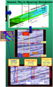 Figure
14.
Figure
14.