![]() Click
to view article in PDF format.
Click
to view article in PDF format.
GC3-D Design Philosophy – Part 2: Target Depth*
Bob Hardage1
Search and Discovery Article #40662 (2010)
Posted December 17, 2010
*Adapted from the Geophysical Corner column, prepared by the author, in AAPG Explorer, October, 2010, and entitled “Next Step: Geology Guides the 3-D Design”. Editor of Geophysical Corner is Bob A. Hardage ([email protected]). Managing Editor of AAPG Explorer is Vern Stefanic; Larry Nation is Communications Director. Click for remainder of series: Part 1 Part 3 Part 4
1Bureau of Economic Geology, The University of Texas at Austin ([email protected])
Shallowest Target and Line Spacings
This article is the second of a four-article series – this topic considers Part 2 labeled on the Figure 1 flow chart of 3-D seismic design methodology.
The depth of the shallowest target that must be imaged across a prospect is a key control on the geometry of a 3-D acquisition grid, because that depth dictates the distance that source and receiver lines should be separated. If there is a shallow interface that has a known dip across a prospect, that interface should be imaged even if it is not related to a reservoir – because by making the image dip match the known dip, data processors are assured the static corrections, shallow velocity analyses and other data processing procedures that affect reflector dip and continuity have been correctly done. In other cases, a shallow reflector may need to be imaged so it can be used to make isopach maps. If this shallowest target is at a depth Z1, then a 3-D grid should be structured so that for every stacking bin there are several (at least three or four, and ideally seven or eight) source-receiver pairs that:
● Are separated a distance no greater than Z1.
● Cause reflection points to fall inside the bin.
Figure 2 is a section view showing raypaths that result when a source-to-receiver offset equals the shallow-target depth Z1. If a source-to-receiver offset exceeds Z1, there is a high probability that the illuminating wavefield will be critically refracted at or above Z1 and will not provide a reflection image of the shallow target. Therefore, a 3-D design must ensure that at every stacking bin there are several source-receiver pairs that are separated a distance that does not exceed offset distance Xmin shown on Figure 2, where Xmin=Z1, the depth of the shallowest target. An effective way to ensure this minimum source-to-receiver offset exists is to define the source-line and receiver-line spacings to be approximately the same as, or less than, the shallow-target depth Z1. A good choice is to set the line spacing at one-half or less of the shallow target depth.
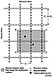
An example of one possible design is shown on Figure 3. This particular geometry illustrates a common design philosophy in which the receiver-line spacing is approximately the same as the shallow-target depth, but for reasons of economy (that is, to reduce the number of source stations per square mile), the source line spacing is slightly larger.
For this design, all source-receiver pairs inside shaded area ABCD satisfy the offset restriction that results in reliable imaging of stratigraphy at, and even slightly above, depth Z1 within that shaded area. Similar overlapping, restricted-offset areas like ABCD extend completely across this particular 3-D grid. Thus, by answering the simple question “what is the shallowest target to preserve in the 3-D image?” a first approximation for source-line and receiver-line spacings that should be used in the 3-D field program can be made.
|
|
The next parameter in the 3-D design is the depth of the primary, or deepest, target that is to be imaged. This depth is labeled Ztar on Figure 2, and the raypath picture shows the source-to-receiver offset range that is particularly critical to imaging a target at this depth involves source-receiver pairs that are separated distances that range from zero to Xmax, where Xmax equals depth Ztar.
Larger source-to-receiver offsets up to a distance of 2Ztar also are important for both data processing and imaging reasons; thus offsets in the range Ztar to 2Ztar also should be created by the recording swath. When a seismic wavefield is generated at a particular source station, the 3-D recording swath is defined as that area spanned by the active receivers that record the seismic response generated at that station.
In concept, these active receiver stations should form a continuous areal coverage completely around the source point and extend at least a distance Ztar (the depth to the primary target) in all directions away from each active source station. In practice, however, only approximations of this type of ideal recording swath sometimes can be created.
For example, if a square swath with side dimensions of 2Ztar causes the number of receiver stations to exceed the channel capacity of the recording system, then a rectangular-shaped swath is commonly used, with the long dimension of the rectangle being 2Ztar to create the required long offset distances, and the narrow dimension being as large as the channel capacity of the recording system will allow.
A typical, rectangular 3-D recording swath is illustrated on Figure 4. The active source stations are all of the source points on source lines S1 through S9 that are between receiver lines R5 and R6, and the recording swath spans all the receivers inside rectangular area ABCD centered about source point E.
To satisfy the raypath requirement shown on Figure 2, either the diagonal distance EC or one of the half-widths EF or EG must be approximately the same as the target depth Ztar.
It is arbitrary as to which of these recording swath dimensions to set equal to Ztar. The number of receiver lines included in swath dimension AD is determined by the receiver-line spacing (Figure 3).
All of the first set of design parameters indicated on Figure 1 now have been calculated using geology to guide the design. The next step is to determine if these choices of source- and receiver-station spacings, source- and receiver-line spacings and recording swath size result in an acceptable stacking fold.
Copyright © AAPG. Serial rights given by author. For all other rights contact author directly. |