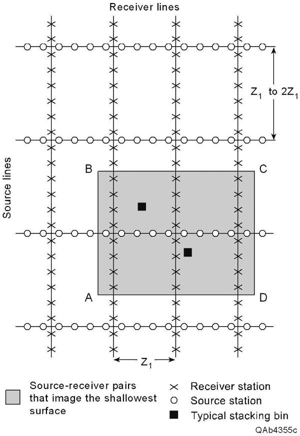
Figure 3. An example of source/receiver-line spacings designed to image a shallow target at a depth Z1. In this example, the distance between the receiver lines is set to a value that equals shallow-target depth Z1. In other instances a designer may elect to set the receiver-line spacing to be 0.5Z1 or less. All of the source-receiver pairs inside the shaded area ABCD have offset separations that are small enough to image stratigraphy at depth Z1. Several (three to five) source-receiver pairs can be found that cause reflection points to be positioned inside each stacking bin, such as the two bins that are highlighted, which creates a continuous, low-fold image across the shallow target. For reasons of economy, the source-line spacing often is made larger than the receiver-line spacing, as is done here, to reduce the number of source stations per square mile.