Click to view poster in PDF format (~6.9 mb).
PSCovenant Oil Field, Central Utah Thrust Belt: Possible Harbinger of Future Discoveries*
By
Thomas C. Chidsey1, Michael D. Laine1, John P. Vrona2, and Douglas K. Strickland2
Search and Discovery Article #10130 (2007)
Posted July 30, 2007
*Adapted from poster presentation at AAPG Annual Convention, Long Beach, California, April 1-4, 2007.
Please refer to Search and Discovery Article #110014 (2005), “Structural Architecture, Petroleum Systems, and Geological Implications for the Covenant Field Discovery, Sevier County, Utah,” by Strickland et al.
1Utah Geological Survey, Salt Lake City, UT ( [email protected] )
2Wolverine Gas and Oil Corporation, Grand Rapids, MI
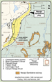
After over 50 years of exploration in the central Utah thrust belt, or “Hingeline,” the 2004 discovery of Covenant oil field proved that this region contains the right components (trap, reservoir, seal, source, and migration history) for large accumulations of oil. To date, 10 producing wells and one dry hole have been drilled from two surface pads. Covenant has produced over 2 million bbls of oil and no gas; the field averages 6400 BOPD.
The Covenant trap is an elongate, symmetric, northeast-trending anticline, with nearly 800 ft of structural closure and bounded on the east by a series of splay thrusts in a passive roof duplex. The eolian Jurassic Navajo Sandstone reservoir is effectively sealed by mudstone and evaporites in the overlying Jurassic Twin Creek Limestone and Arapien Shale. Oil analysis indicates a probable Mississippian source – oil derived and migrated from rocks within the Hingeline region.
Cores from the Navajo Sandstone display a variety of eolian facies (dune, interdune, lake/playa, fluvial/wadi), fracturing, and minor faults which, in combination, create reservoir heterogeneity. Reservoir sandstone is 97% frosted quartz grains (bimodal grain size), with some quartz overgrowths and illite. The net reservoir thickness is 424 ft over a 1600-ac area. Porosity averages 12%; permeability is 100 mD. The drive mechanism is a strong water drive; water saturation is 38%. A thorough understanding of all the components that created Covenant field will determine whether it is a harbinger of additional, large oil discoveries in this vast, under-explored region.
|
|
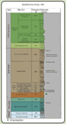
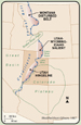
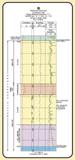
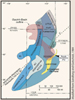
The central Utah thrust belt, or “Hingeline,” has seen cycles of petroleum exploration for the past 50 years because explorationists viewed the geology as a natural extension of productive thrust belt-style structures in northern Utah and southwestern Wyoming. Early unsuccessful efforts tested anticlines identified from surface mapping and seismic reflection data. The lack of a Cretaceous source seemingly was to blame for these failures. The 2004 discovery of Covenant oil field proved that this region contains the right components (trap, reservoir, seal, source, and migration history) for large accumulations of oil. To date, 10 producing wells and one dry hole have been drilled from two surface pads. Covenant has produced over 3 million bbls of oil and no gas; the field averages 5500 BOPD from the Jurassic Navajo Sandstone. The OOIP is estimated at 100 million bbls; the estimated recovery factor is 40%. The Covenant trap is an elongate, symmetric, northeast-trending, fault-propagation anticline formed during the Sevier orogeny (Late Jurassic-Early Tertiary), with nearly 800 ft (240 m) of structural closure. The structure formed above a series of splay thrusts in a passive roof duplex along the “blind” Gunnison-Salina thrust and west of a frontal triangle zone within the Jurassic Arapien Shale. The Jurassic Twin Creek Limestone and Navajo Sandstone are repeated due to an east-dipping back thrust detachment within the structure. This back-thrust forms a hanging wall cutoff along the west flank and north-plunging nose of the fold. Only the first Navajo (and possibly the Twin Creek) is productive. The eolian Navajo Sandstone reservoir is effectively sealed by mudstone and evaporites in the overlying Jurassic Twin Creek Limestone and Arapien Shale. Oil analysis indicates a probable Mississippian source – oil derived and migrated from rocks within the Hingeline region. Cores from the Navajo Sandstone display a variety of eolian lithofacies (dune, interdune, lake/playa, fluvial/wadi), fracturing, and minor faults which, in combination, create reservoir heterogeneity. Reservoir sandstone is 97% frosted quartz grains (bimodal grain size), with some quartz overgrowths and illite. The net reservoir thickness is 424 ft (129 m) over a 960 acres (390 ha) area. Porosity averages 12%; permeability is ≤100 mD. The drive mechanism is a strong water drive; water saturation is 38%. A thorough understanding of all the components that created Covenant field will determine whether it is a harbinger of additional, large oil discoveries in this vast, under-explored region.
(Figures 5-8)
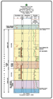
Discovery Well Wolverine Gas & Oil Corporation Kings Meadow Ranches No. 17-1 SENW Sec. 17, T.23S., R.1W, Sevier County, Utah TD – 9382 ft Completed – November 3, 2004 Producing reservoir – Jurassic Navajo Sandstone IPF – 708 BOPD, 1 MCFGPD, 20 BWPD
Reservoir Data Productive area – 960 acres Gross pay – 487 ft Net pay – 424 ft Net to gross – 0.87 Hydrocarbon column – 450 ft Average porosity – 12% Permeability – up to 300 mD Water saturation – 38% Water resistivity – 0.279 Ohm-m @ 77oF, 26,035 TDS BHT – 188oF Type of drive – strong water drive Initial reservoir pressure – 2630 psi
Production and Reserves Producing wells – 10 Dry holes – 1 Abandoned producers – none Monthly production (November, 2006) – 166,036 BO & 49,810 BW Cumulative production (as of December 1, 2006) - 2,938,869 BO & 527,076 BW OOIP – 100 million bbls Estimated recovery factor – 40%
(Figures 9-10)
Covenant Field Reservoir: Eolian Jurassic Navajo Sandstone (Figures 11-22)
Navajo Sandstone Lithofacies Recognized in Core from the Federal No. 17-3 Well T – Thick: dune deposits containing the large-scale, trough, planar, or wedge-planar cross-beds (35 to 40°) commonly recognized as classical eolian dune features. Very well to well-sorted, dune and avalanche deposits. Sand layers greater than 0.5 cm thick in core. The brink to the toe of the dune slipface consists of thin, graded, tabular grainfall laminae (rarely preserved in the core) and thick, subgraded, avalanche laminae. The “thick” classification is correlated to avalanche deposits. Porosity ranging from 5 to 15%, and permeabilties typically from 7 to 300 mD. TC – Thin Continuous: sand layer continuously bedded, trough, planar, or wedge-planar cross-beds less inclined than the thick lithofacies (20 to 35°), and less than 0.5 cm thick in core. Moderately well to poorly sorted with more clay cementation than the “TD” lithofacies. The TC lithofacies can occur within the thick and Thin Discontinuous lithofacies making the TC lithofacies a transitional phase. All porosities are under 10% and permeabilites range from 1 to 30 mD TD – Thin Discontinuous: flat lying bedding less than 0.5 cm thick in core containing wind ripples, and some cross-bedding (0 to 20°). Moderately to poorly sorted with greater carbonate cement than TC layer. Thin discontinuous tightly packed, reworked ripple strata are representative of dune toe lithofacies. Low porosities and permeabilites are characteristic. WBH – Interdunal: low-angle to horizontal laminae or distorted bedding consisting of very fine to fine-grained, thin, poorly sorted sandstone, siltstone, and shale dominated by carbonate cement. Beds may contain wind ripples or fluvial characteristics (scour). Very low porosities and permeabilities. Interdunal fluvial characteristics indicate sheet flow or flooding events in a fluvial/wadi while other deposits suggest wet, playa or lacustrine conditions. M – Massive: homogenized sandstone layers showing no distinct sedimentary structures or laminations. This lithofacies probably formed by water-saturated sand. FB – Fault Breccia: Breccia resulting from a fault and fracture zones running through the core of the Federal No. 17-3 well.
Lithology – very fine- to medium-grained (1/16 mm to ½ mm), quartz sandstone; 97%, white or clear quartz grains with varying amounts of K-feldspar. Sand Grains – subangular to subrounded, very well to well-sorted, usually frosted. Pore Types – primary intergranular, fracture. Grain Density – 2.651 g/cm3 Diagenesis – minor overgrowths of quartz; some authigenic clay mineralization has occurred in the form of grain-coating, pore-bridging, and fibrous illite; some ferroan (?) dolomite and fractured, corroded K-feldspar are also present.
(Figures 23-24)
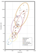
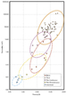
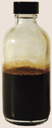
Oil gravity – 40.5º API Color – dark brown Viscosity – 4.0 centistokes @ 77ºF Pour point – 2.2ºF Sulfur – 0.48% Nitrogen – 474 parts per million Stable carbon-13 isotopes – -29.4‰ (saturated) and -29.0‰ (aromatic) hydrocarbons Pristane/phytane ratio – 0.96
(Figures 25-26)
(Figures 27-28)
Baseline DGSI, 2005, Basic crude oil characteristics and biomarker analysis from the Kings Meadow Ranches No. 17-1 well, Covenant field, Sevier County, Utah: Utah Geological Survey Open-file Report 467, 15 p. Gibson, R.I. 1987, Basement tectonic controls on structural style of the Laramide thrust belt interpreted from gravy and magnetic data, in Miller, W.R., ed., The thrust belt revisited: Wyoming Geological Association 38th Field Conference Guidebook, p. 27-35. Hamblin, W.K., 2004, Beyond the visible landscape – aerial panoramas of Utah’geology: Brigham Young University, Department of Geology, p. 232-233. Hintze, L.F., 1980, Geologic map of Utah: Utah Geological Survey Map M-A-1, 2 sheets, scale 1:500,000. Hintze, L.F., 1993, Geological history: Brigham young University Geology Studies Special Publication 7, 202 p. Hintze, L.F. Willis, G.C., Laes, D.Y.M., Sprnkel, D.A., and Brown, K.D., 2000, Digital geologic map of Ytah: Utah Geological Survey Map 179 DM, 17 p. scale 1:500,000. Kocurek, G., and Dott, R.H., Jr., 1983, Jurassic paleogeography and paleoclimate of the central and southern Rocky Mountains region, in Reynolds, M.W., and Dolly, E.D., eds., Symposium on Mesozoic paleogeography of west-central U.S.: SEPM Rocky Section, p. 101-116. Lillis, P.G., Warden, Augusta, and King, J.D., 2003, Petroleum systems of the Uinta and Piceance basins – geochemical characteristics of oil types, in Petroleum systems and geologic assessment of oil and gas in the Uinta-Piceance province, Utah and Colorado: U.S. Geological Survey Digital Data Series DDS-69-B, Chapter 3, 25 p. Moyle, Richard W., 1958, Paleoecology of the Manning Canyon Shale in central Utah: Brigham Young University Research Studies, v. 5, no. 7, 86 p., 7 plates. Peterson, J.A., 2001, updated 2003, Carboniferous-Permian (late Paleozoic) hydrocarbon system, Rocky Mountains and Great Basin U.S. region—major historic exploration objective: Rocky Mountain Association of Geologists Open-field Report, 54 p. Picard, M.D., 1975, Facies, petrography and petroleum potential of Nugget Sandstone (Jurassic), southwestern Wyoming and northeastern Utah, in Bolyard, D.W., ed., Symposium on deep drilling frontiers of the central Rocky Mountains: Rocky Mountain Association of Geologists Guidebook, p. 109-127. Sandberg, C.A., and Gutschick, R.C. 1984, Distribution, microfauna, and source-rock potential of Mississippian Delle Phosphatic Member of Woodman Formation and equivalents, Utah and adjacent states, in Woodward, Jane, Meissner, F.F., and Clayton, J.L., eds., Hydrocarbon source rocks of the greater Rocky Mountain region: Rocky Mountain Association of Geologists Guidebook, p. 135-178. Schelling , D.D., Strickland, D., Johnson, K.R., Vrona, J.P., Wavrek, D.A., and Reuter, J., 2005, Structural architecture and evolution of the central Utah thrust belt – Implications for hydrocarbon exploration (abs.): AAPG Annual Convention Official Program with Abstracts, v. 17, non-paginated. Sofer, Zvi, 1984, Stable carbon isotope compositions of crude oils – Application to source depositional environments and petroleum alteration: AAPG Annual Convention Official Program with Abstracts, v. 6, p. A110. Sprinkel, D.A., and Chidsey, T.C., Jr., 1993, Jurassic Twin Creek Limestone, in Hjellming, C.A., ed., Atlas of major Rocky Mountain gas reservoirs: New Mexico Bureau of Mines and Mineral Resources, p. 76. Utah Division of Oil, Gas and Mining, 2006, Oil and gas production report, December: Online (http://ogm.utah.gov/oilgas/PUBLICATIONS/Reports/PROD_book_list.htm), accessed April 19, 2007. Villien, A., and Kligfield, R.M., 1986, Thrusting and synorogenic sedimentation in central Utah, in Peterson, J.A., ed., Paleotectonics and sedimentation in the Rocky Mountain region: AAPG Memoir 41, p. 281-306.
Funding for this ongoing research was provided, in part, under the Preferred Upstream Management Program of the U.S. Department of Energy, National Energy Technology Laboratory, Tulsa, Oklahoma, contract number DE-FC26-02NT15133. Support was also provided by the Utah Geological Survey (UGS) and Wolverine Gas & Oil Corp (WGO). Field cores were described by L.F. Krystinik, geologic consultant. Jake DeHamer, WGO, interpreted core petrophysical data. The poster design was by Liz Paton of the UGS. James Parker, Liz Paton, Sharon Wakefield, and Cheryl Gustin of the UGS prepared the figures; Brad Wolverton of the UGS Core Research Center assisted with core photography. |