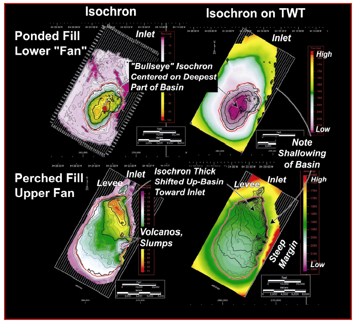
Figure 3. Maps showing illustrating differences between ''Ponded'' and ''Perched'' basin filling units. On the left are isochron maps showing the thickness and extents of the Lower Fan and Upper Fan. On the right are the thickness contours superimposed on TWT (color) of the basal surfaces of these units. Note: a) the shallowing of the basin through time b) the relative conformity of thickness and bathymetric contours in the ''Ponded'' case, and c) the disconformity between thickness and bathymetric contours in the ''Perched'' case.