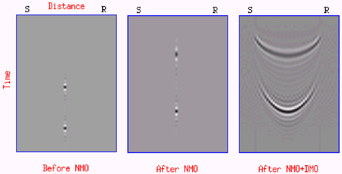
Figure 10. This numerical example illustrates the effect of NMO and DMO on a trace with two spikes, or reflection events. The spikes are shown on the left surrounded by a bunch of zero traces. The source and receiver locations are denoted by S and R, respectively. NMO shifts the spikes up in time, but only on the same trace (middle). DMO throws the NMO’d spike amplitude out along a curve to handle all possible dips. This curve is called the DMO smile, or DMO ellipse, or DMO impulse response. Notice the DMO smile only lives between the original source and receiver positions.