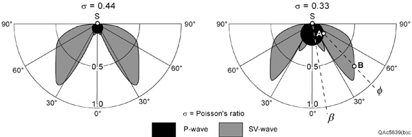
Figure 1. P-wave and SV-wave radiation patterns produced when a vertical impulse is applied to the Earth
surface at source station S. These patterns define the relative strengths of the illuminating wavefields, not
the geometrical shapes of the wavefields. For example, at take-off angle F, the strength of the downgoing
P wavefield is A, and the strength of the SV wavefield is B. The quantity s represents the Poisson’s ratio
of the Earth half space.