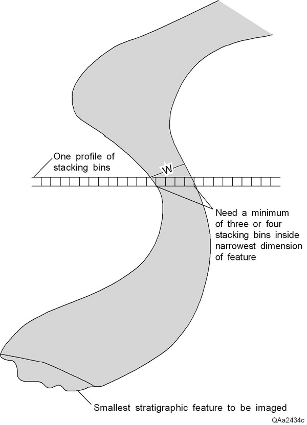
Figure 3. Example of a narrow feature that needs to be seen in a 3-D image. The first parameter that has to be defined in this 3-D seismic design method is the smallest (narrowest) horizontal dimension of a feature that must be seen in the 3-D data volume. For purposes of illustration, it is assumed the narrowest feature that is to be interpreted is a meander channel. At least three, and ideally four, stacking bins (seismic traces) must lie within the narrowest dimension W of this channel if the channel is to be reliably seen in the seismic image during workstation interpretation. Once this minimum channel width W is defined, the dimensions of the stacking bins are also defined, those bin dimensions being no wider than W/3, and ideally, they should be W/4 or less.