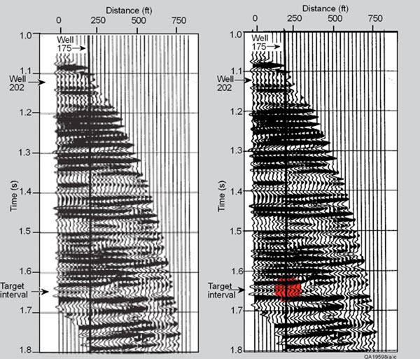
Figure 3. VSP data acquired in well 202 to create an image spanning across well 175. These data have been processed to create stacking bins 25 feet wide. Reservoir units A, B and C defined on Figure 1 are positioned in the reflection peak labeled "Target interval." Well 202, the VSP receiver well, is positioned at the first image trace on the left. The highlighted reflection waveform change that occurs beginning at an image position approximately 50 feet to the left of well 175 is assumed to be the compartment boundary between the two wells.