Click on image to view enlargement.
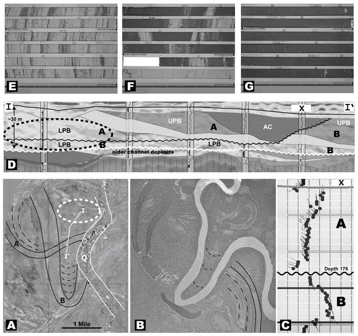
Figure 3. Reservoir geometry and characterization. A. Seismic time slice over the study area. Highlighted are two meanders labeled as “A” and “B” channels. Scroll bars are highlighted by black dashed lines and terminal portions (abandoned channel-fill deposits) with black solid lines. A Quaternary channel deposit that has incised into the McMurray Formation is outlined and labeled “Q”. White line (I-I’) shows the position of the geological section presented in Figure 3D. Vertical well “X” (see Figure 3C) is marked by a small white cross (x). A big oval (white dashed lines) encircles an area with the best reservoir sands. B. Aerial photo of Fly River in Papua New Guinea shows similar geometries to those revealed by seismic in Figure 3A. C. Dipmeter data from well “X”. Dip orientation determines the stratigraphic order of stacked channels A and B. D. Geological cross-section showing the relationship of stacked point bar “A” and “B” deposits. Black wavy line shows the bottom of the channel “A” whilst white wavy line indicates the bottom of the channel “B”. Note that lower point bar (LPB) portions of channels “A” and “B” are stacked in the northern portion and that only channel “B” exists in the southern portion of the section. Areas not shaded represents thick continuous sands and bottom channel breccia deposits – expected reservoir type I quality. Light shaded areas are sandy IHS deposits of the upper point bar (UPB) deposit – expected reservoir type II quality. Darker shaded areas are mud dominated IHS within the UPB and solid dark grey-color-filled areas are muddy IHS of the abandoned channel-fill deposit (AC). The last two are non-reservoir facies. The dashed sphere indicates the best position for future SAGD development where two LPB deposits are stacked yielding approximately 30 meters vertically continuous sand pay. Note remnants of some older deposits below channel A and B deposits. E, F, and G. Core images of abandoned channel-fill, sandy IHS (UPB deposit), and apparently “massive” clean sand from LPB deposit, respectively. They represent non-reservoir, reservoir type 2 and reservoir type 1 deposit, respectively.