Fracture Development in  Salt
Salt Dome Caprock,
Hardin County, Texas*
Dome Caprock,
Hardin County, Texas*
By
Alfred Lacazette1, Andrew R. Thomas2, and Dennis Kuhfal3
Search and Discovery Article #50058 (2007)
Posted November 20, 2007
*Adapted from extended abstract prepared for
presentation at AAPG Annual Convention, Long Beach, California, April 1-4, 2007
1NaturalFractures.com
LLC, Houston, TX ([email protected])
2Chevron
Energy Technology Company, Houston, TX
3Chevron
Mid-Continent Business Unit, Houston, Texas
Introduction
The first East
Texas oil boom was based on production from fractured limestone saltdome caprock.
Limestone caprocks are formed during salt dome ascent by:
·
Accumulation of disseminated anhydrite due to salt dissolution,
·
Conversion of anhydrite and hydrocarbon to calcite and sulfides by
sulfate reducing bacteria.
Fracture
development in salt-dome caprock is understood poorly because caprock production
was exhausted long before the advent of modern reservoir characterization
technologies. This contribution describes a detailed study of the fracture
system of the Sour Lake Field caprock (discovered in 1902) using oriented core,
borehole image logs, crosswell seismic tomography, dipole sonic logs,
petrography, isotopes, and other modern methods.
|
uIntroduction
uFigure
captions
uData
set
uResults
uApplication
uReferences
uIntroduction
uFigure
captions
uData
set
uResults
uApplication
uReferences
uIntroduction
uFigure
captions
uData
set
uResults
uApplication
uReferences
uIntroduction
uFigure
captions
uData
set
uResults
uApplication
uReferences
uIntroduction
uFigure
captions
uData
set
uResults
uApplication
uReferences
|
Figure
Captions
|
 |
Figure 1. Location of Sour Lake Field
(from Halbouty and Hardin, 1955) and contour map on top of salt
(from Looff, 2001). |
|
 |
Figure 2. Caprock layers in thin-section
at sample depth of 1737 ft. in the 816 well. The dark bands
contain bitumen and very fine-grained calcite crystals. The
bitumen is composed of heavy hydrocarbon that the bacteria could
not consume. The cyclic layering of bitumen and coarse calcite
is interpreted to represent cycles of bacterial growth and
quiescence in the caprock accretion cycle. Thin-section
photomicrograph, plane-polarized light; scale bar at lower right
is 0.8mm. |
|
 |
Figure 3. Carbon and oxygen isotopic
composition, Sour Lake limestone and anhydrite fracture zones.
Plot shows a mixing line that we interpret to result from mixing
of meteoric water and formation water influenced by
sulfate-reducing bacteria. |
|
 |
Figure 4. Paleostress analysis of faults
measured in core and the image log show vertical shortening and
horizontal extension of the caprock, indicating that the caprock
was stretched by dome growth. The intermediate axis is roughly
parallel to the regional maximum compressive stress orientation
suggesting that the regional stress state overprints the local
stresses caused by dome emplacement. This stretching also
produces extensional fractures (not shown). |
|
 |
Figure 5. Diagenetic shrinkage at a
minor fault in anhydrite.
Left - The surface of a minor fault in the anhydrite layer shows
polygonal extension cracks that are widest at the fault surface.
Right - Photomicrograph of thin-section cut at right angles to
both the fault and one of the extension cracks. Calcite is
stained pink; anhydrite is white; epoxy is blue. The fault
surface (left side) is completely altered to calcite. Both
calcite alteration and the crack die-out away from the fault
surface. Note residual bitumen layer parallel to the fault
surface, resulting from oil movement along the fault. Bacteria
consume the hydrocarbon, convert sulfate to sulfide, generate
bicarbonate, and back precipitate calcite in the presence of
calcium. Conversion of anhydrite to calcite results in a 20%
molar volume reduction. This volume change shrinks the caprock
and produces extensional fractures that contribute to the
fracture system. |
|
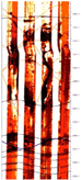 |
Figure 6. FMI image of a pod of porous,
fractured anhydrite in the 816 well between 1800 and 1900 feet.
|
|
 |
Figure 7. Geologic interpretation of the
crosswell velocity and diffraction tomograms between the 795 and
816 wells, based on well data (core, image logs, crossed-dipole
sonic logs, and conventional logs). The yellow circle marks
where the horizontal well penetrated the plane of the tomogram.
Prominent faults are shown as heavy dashed lines with their
apparent dip angles as measured in the plane of the tomogram.
Vertical:horizontal scale = 1:1. |
Data Set
The
following data was collected:
·
A vertical pilot hole (the 816) was drilled and
continuously cored from the overlying shale, through the caprock, and
into the underlying halite. A full suite of logs was collected in the
816, including an electrical image log and a crossed-dipole sonic log.
·
A crosswell tomogram was shot between the 816 and an
existing well (the 795) that had a suite of conventional logs.
·
A horizontal well was drilled through the plane of the
tomogram, and was oriented to optimally sample the fracture network
based on observations in the pilot hole.
·
The horizontal well was logged and an image log was
collected.
Results
We find
that the caprock fracture system developed during caprock growth and
that development of the fracture system is linked to salt-dome movement.
The caprock was fractured both by faulting and extensional fracturing
resulting from dome emplacement and by mineral volume changes occurring
during conversion of anhydrite to calcite. Isotopic data from the
limestones (d18O: -4
to -8 PDB, and d13C:
-11 to -31 PDB) suggest that fluids evolved from deep bacterial to mixed
meteoric during dome ascent. Paleostress analysis based on fault-slip
kinematics and extensional fracturing shows that caprock strain was due
to dome inflation and that this expansion bears an overprint of the
neotectonic (present-day) stress field. We interpret that previously
unrecognized pockets of fractured limestone exist deep within the Sour
Lake anhydrite layer and that these pockets represent a significant
positive modification of traditional salt dome caprock reservoir volume.
Some of these pockets are both sampled by wells and imaged on the
crosswell tomogram. The fractured limestone pockets within the anhydrite
resulted from bacterially-mediated diagenetic reactions that occurred
when petroleum and brine flowed through faults resulting from dome
expansion.
This
study targeted an undrilled area that was thought to represent an
isolated fault block. The caprock was found to have a very well
developed fracture system and to have excellent fracture porosity and
permeability. Although the core from the pilot hole was oil soaked and
although there were numerous oil shows during drilling of the horizontal
well, the horizontal well tested ~30,000 barrels of water/day and little
oil. We speculate that the fault block is not isolated and that the oil
was produced and/or flushed-out by disposal water that was injected
elsewhere in the dome.
Application
The
conditions that produced the fracture porosity and permeability at Sour
Lake are the same processes that operate on all salt domes that develop
caprock. Consequently, Sour Lake could be a typical example of a caprock
fracture system and results of this study might be applied more broadly
to caprocks in mobile salt basins. This study has direct application to
oil and gas operations and construction of storage facilities in salt
domes. The discovery of porous volumes within the anhydrite layer is
especially significant because until now only the limestone layer was
thought to have porosity and permeability.
References
Halbouty, M.T., and G.C. Hardin, Jr., 1955, Factors
affecting quantity of oil accumulation around some Texas Gulf Coast
piercement-type salt domes: AAPG Bulletin, v. 39, p. 697-711.
Looff,
K., M., 2001, Recent salt related uplift and subsidence at Sour Lake
salt dome, Hardin County, Texas: GCAGS Transactions, v. 51, p. 187-194. dome, Hardin County, Texas: GCAGS Transactions, v. 51, p. 187-194.
Return to top.
|
 Click to view article in PDF format (~2.5 mb).