Calichification-Induced Structures in the Edwards Plateau, Texas
James J. Willis1 and Kristen M. Willis1,2
1Odyssey International, LLC, 7190-C Cemetery Hwy., St. Martinville, Louisiana 70582
2Department of Geology, University of Louisiana at Lafayette, P.O. Box 44530, Lafayette, Louisiana 70504
EXTENDED ABSTRACT
Introduction
Calichification, a soil-forming process by mineralization of calcium carbonate, is widespread in the Edwards Plateau region, Texas. Overall, the Edwards Plateau is characterized by relatively flat strata with dips commonly measuring only a few feet per mile (a fraction of a degree), although local dips at or near fault zones, dissolution/collapse zones, etc. may be much more significant. The emplacement of caliche, as an expansional process with addition of new material often forcing significant response and accommodation by adjacent or nearby strata, in the Edwards Plateau provides an additional means of creating structures that disrupts the typical flat structure, in some cases quite dramatically.
A common response to calichification in the Edwards Plateau is the uplifting of near-surface strata on hill sides. Caliche preferentially (though not exclusively) emplaced in argillaceous units near the surface slope has forced overlying strata upward, yielding local dips (several degrees or more) into the hill side, whereas rocks occurring either deeper or laterally further into the hill side exhibit little to no caliche and thus maintain original, near-horizontal orientation. The opposite side of a given hill may likewise exhibit local near-surface calichification and inward-dipping strata, yielding an overall syncline across the hill itself and anticlines at valley lows.
In addition to vertical forcing and movement, significant lateral forces may be generated as well due to caliche formation. In the Edwards Plateau, calichification-induced horizontal compression is manifested in a diversity of shallow, localized deformation fabrics, including parallel- and similar-style folds, tepee structures, disharmonic folds, thrust faults, and so forth. Examples of overturned beds can even be observed. These fabrics share remarkable similarity to forms typical of tectonic compressional fabrics, which makes their formation, not by tectonic stresses, but rather by a soil-forming process all the more intriguing and interesting.
Illustrative Figures and Discussion
Figure 1 illustrates an index map of the Junction-Kerrville area, Texas, and location of calichification-induced compressional structures along U.S. Interstate Highway 10 (I-10). Although examples occur at several localities, this paper focuses on those structures exposed in road cuts at mile marker 484, indicated by the green hexagon.
Figure 2 shows an outcrop photograph of exposures along the north side of the westbound lanes of I-10, illustrating some of the compressional structures formed as a result of caliche precipitation. Note mile marker 484 sign for location reference.
Figure 3 presents an index photograph of an anticlinal structure located along the north side of the westbound lanes of I-10. This structure occurs westward along the same outcropping as Figure 2. The lower half of the outcrop is dominated by extensive masses of caliche, which have significantly disrupted original stratigraphic layers, leading to an irregular outcrop geometry. The upper half of the outcrop, while still exhibiting evidence of caliche emplacement, retains more consistent layering, emphasized especially by two dark-colored chert-bearing horizons. Boxes indicate approximate locations of Figures 4, 5, 6, 7.
Figure 4 provides a close-up of the primary anticline depicted in Figure 3. Flank dips range up to several tens of degrees near the core of the anticline, decreasing outward laterally into broad open synclines. The anticline detaches downward into a layer located just above the lower disrupted zone. Boxes on the figure indicate approximate locations of Figures 6 and 7, which respectively highlight a small thrust fault developed near the anticlinal flexure, and the area of extensive calichification and resultant disruption.
Figure 5 displays a a close-up of small-scale thrust fault and associated fold located near the axis of a broad syncline (for location see Figure 3). The thrust fault dies out upsection, transitioning into a small-scale overturned fold. Considering that the general dip in the Edwards Plateau is commonly measured in units of feet per mile (e.g., Rose, 1972; Willis et al., 2001), it is remarkable that calichification, a soil forming process, has generated a local dip of approximately 120°.
Figure 6 provides a close-up of a small-scale thrust fault located near the anticlinal flexure depicted in Figures 3 and 4.
Figure 7 presents a close-up of the lower disrupted zone depicted in Figure 3. Caliche occurs widespread throughout this zone, often as irregular masses. Caliche emplacement has caused significant deformation of stratigraphic layers in this zone, often to the point where correlation of original layers is quite difficult. In this example, a correlative horizon (marked by yellow line) is displaced along several reverse/thrust faults, as well as two small normal faults—fault cutoffs indicated by blue circles. In this photograph, comparison of the actual length of the horizon (which equates to an original horizontal length, lo) versus horizontal dimension (width) of the photograph (equating to final length, lf) yields a calculation of approximately 18% horizontal shortening (compressional) strain. Calculations elsewhere yield different numerical results, but nonetheless indicate significant shortening.
Figure 8 shows an outcrop photograph of disharmonic structures along the north side of the westbound lanes of I-10 near mile marker 484. A prominent Z-fold can be observed with a well-defined overturned limb. The boxed area highlights a complex fault-related fold illustrated further in Figure 9. Strata locally above and below these two highlighted features are essentially through-going, although additional small-scale disruptions are also present.
Figure 9 illustrates a close-up of the small-scale structure highlighted in Figure 8. The dominant feature is a right-vergent thrust fault with an associated left-vergent backthrust, together representing a conjugate pair and each with associated folding. The main thrust fault resulted in local overturning on its upper plate. Overall the two faults developed above a small-scale anticline, themselves in turn forming a local anticline in overlying strata. An affiliated syncline is also present. The syncline exhibits an open interlimb angle in its lower region (e.g., primary marked horizon), but tightens upsection dramatically (e.g., locally mapped horizon), before detaching further upsection, representing an overall classic parallel-style fold geometry (Dahlstrom, 1969).
Figure 10 provides an outcrop photograph of disharmonic structures along the south side of the eastbound lanes of I-10 near mile marker 484. Figures 11 and 12 highlight dominant features.
Figure 11 presents a close-up of a well-defined parallel-folded syncline (for location see Figure 10). Note how the lower layers are broadly folded, whereas the upper layers exhibit a tighter nature and are displaced by a thrust fault in the core of the syncline. The uppermost marked horizon continues essentially undeformed across the photograph, indicating that the fold has detached below.
Figure 12 shows a close-up of well-defined parallel-folded anticline (for location see Figure 10). In this anticlinal example of a parallel fold, note how the upper layers are broadly folded whereas the lower layers are more tightly folded and are offset by two thrust faults. The lowermost marked horizons continue essentially undeformed across the photograph, indicating that the fold has detached above. In typical parallel folding, anticlines tighten downward to detachment, whereas synclines tighten upward to detachment (e.g., Dahlstrom, 1969; Willis and Groshong, 1993). Often subsidiary structures develop on the flanks of parallel folds (e.g., Brown, 1988; Willis and Groshong, 1993), an example of which is marked on the photograph.
Figure 13 is a close-up of a small-scale S-fold, which is located along the north side of the westbound lanes of I-10. The resistant cherty layer has deformed in a competent manner, breaking into segments that have been rotated (especially the now overturned central segment), whereas the overlying and underlying limey units have behaved incompetently.
Figure 14 demonstrates a classic parallel-folded syncline. In this example, the lower layers are synclinally folded, whereas the upper layers exhibit a near horizontal nature, with an intervening incompetent layer serving as the detachment zone. Notice that the incompetent layer has been thinned dramatically on the flanks.
Figure 15 depicts another parallel-folded syncline, albeit with a bit more complexity than the Figure 14 example. This example also exhibits a transition between synclinally-folded strata passing through a detachment zone into overlying near horizontal strata. Overall the syncline exhibits a classic parallel geometry, whereby the lower strata (i.e., the lowermost highlighted horizon) are gently folded and higher strata are more tightly folded (e.g., note the sharp chevron fold at the uppermost highlighted horizon). Some decoupling between individual layers within the syncline can be observed, as the middle mapped horizon, representing the top of a more competent unit, is much more deformed than its base. The syncline then broadens, before tightening again at the uppermost mapped horizon.
Figure 16 provides examples of subsidiary folds developed in the synclinal core. Volumetric constraints develop in the cores of parallel folds—in synclines in particular this “excess” volume can be resolved by a variety of means, including porosity reduction and out-of-the-syncline transfer of material (Willis, 1993). Material can be transferred up the adjacent flanks (e.g., the small-scale subsidiary flank fold in Figure 12, and the small-scale thrust fault in Figure 15) and/or further upward in the synclinal core (as pop-out folds depicted here or along synclinal-hinge faults).
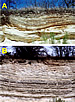
Figure 17 shows how calichification can result in vertical wedging of strata, a mode of deformation in addition to compressional features aforementioned. Figure 18 illustrates how wedging can form tepee structures. Wedging in the Edwards Plateau region appears most common by preferential caliche mineralization along argillaceous units (Lock et al., 2001). Near-surface calichification forces overlying strata upward, yielding a local dip pattern opposite to the slope direction, as depicted in Figure 17A. In valley lows it is not uncommon for anti-slope dip to occur by wedging on both valley slopes, yielding a local anticlinal geometry (Fig. 17B), with intervening synclines between valleys. Figure 17A is an example from the Edwards Formation along I-10, and Figure 17B is an example from the Langtry Formation (basal Austin Chalk) along U.S. Highway 90 (US-90) west of Langtry, Texas.
Figure 18 provides an example of a tepee structure in the Boquillas Formation west of Del Rio, Texas, along US-90, whereby wedging occurred outward from a central fracture, yielding the tepee form, as depicted conceptually in Figure 18B. This is but one type of tepee structure (see Kendall and Warren, 1987, which provides an excellent summary of modes of tepee formation), and it is not a compressional anticline. Rather this anticlinal form resulted from differential caliche thickness away from the central location.
Summary
Although the Edwards Plateau of Texas is characterized by nearly flat stratigraphy, with dips commonly measured in terms of feet per mile, as opposed to degrees, local calichification—a soil-forming process—has locally resulted in quite significant disruption and deformation, including evidence of intense horizontal compression. Examples in the Kerrville-Junction area in outcrops along the I-10 corridor in the Kerrville-Junction area are quite spectacular, especially those around mile marker 484. The lateral push from emplacement of caliche resulted in formation of a variety of contractional folds, including parallel, similar, and overturned folds, as well as thrust faults. Vertical wedging represents an additional mode of deformation caused by local calichification. If you are ever burdened with the 880-mile drive along I-10 through Texas, have a look in the Kerrville-Junction area, which not only hosts these calichification structures, but also exposes an evaporite weld (see Willis et al., 2001)—you’ll likely appreciate the break from the otherwise monotonous flat stratigraphy that characterizes much of the drive!
REFERENCES CITED
Brown, W. G., 1988, Deformational style of Laramide uplifts in the Wyoming foreland: Geological Society of America Memoir 171, Boulder, Colorado, p. 1-25.
Dahlstrom, C. D. A., 1969, The upper detachment in concentric folding: Bulletin of Canadian Petroleum Geology, v. 17, p. 326-346.
Kendall, C. G. St. C, and J. Warren, 1987, Review of the origin and setting of tepees and their associated fabrics: Sedimentology, v. 34, p. 1007-1027.
Lock, B. E., S.-J. Choh, and J. J. Willis, 2001, Tepees and other surficial deformation features of Cretaceous rocks in Central and West Texas, resulting from late Cenozoic caliche formation: Gulf Coast Association of Geological Societies Transactions, v. 51, p. 173-185.
Rose, P. R., 1972, Edwards Group, surface and subsurface, Central Texas: Texas Bureau of Economic Geology Report of Investigations 74, 198 p.
Willis, J. J., 1993, Foreland deformation: Ph.D. dissertation, Baylor University, Waco, Texas, 560 p.
Willis, J. J., and R. H. Groshong, Jr., 1993, Deformational style of the Wind River uplift and associated flank structure, in W. R. Keefer, W. J. Metzger, and L. H. Godwin, eds., Oil and gas and other resources of the Wind River Basin, Wyoming: 1993 Wyoming Geological Association (Casper) / U.S. Bureau of Indian Affairs (Washington, D.C.) Special Symposium volume, p. 337-375.
Willis, J. J., B. E. Lock, K. C. Cornell, and D. A. Ruberg, 2001, An exposed evaporite weld and related deformational structures, Edwards Plateau, I-10 corridor, Kerrville-Junction-Sonora area, Texas: Gulf Coast Association of Geological Societies Transactions, v. 51, p. 389-397.
Willis, J. J., and K. M. Willis, 2009, Calichification-induced structures in the Edwards Plateau, Texas: Gulf Coast Association of Geological Societies Transactions, v. 59, p. 797-811.
| |
| |
| |
| Figure 4. Close-up of the primary anticline depicted in Figure 3. |
| |
| |
| Figure 7. Close-up of the lower disrupted zone depicted in Figure 3. |
| |
| Figure 9. Close-up of the ft-scale structure highlighted in Figure 8. |
| |
| |
| |
| |
| |
| |
| |
| |
| (FACING PAGE) Figure 18. (A) Example of tepee structure in the Boquillas Formation west of Del Rio, Texas, along US-90, whereby wedging occurred outward from a central fracture yielding the tepee form, as depicted conceptually in (B) (from Lock et al., 2001, reproduced with permission of the Gulf Coast Association of Geological Societies). Arrows in (A) highlight a layer that from the gentle-dipping margin toward the tepee core exhibits significant caliche-related thickening. |


AAPG Search and Discover Article #90093 © 2009 GCAGS 59th Annual Meeting, Shreveport, Louisiana