![]() Click to view article in PDF format.
Click to view article in PDF format.
GC![]() 3-D
3-D![]() Design Philosophy – Part 1: Target Size*
Design Philosophy – Part 1: Target Size*
Bob Hardage1
Search and Discovery Article #40661 (2010)
Posted December 17, 2010
*Adapted from the Geophysical Corner column, prepared by the author, in AAPG Explorer, September, 2010, and entitled “First of a Series: ![]() 3-D
3-D![]() Design Philosophy”. Editor of Geophysical Corner is Bob A. Hardage ([email protected]). Managing Editor of AAPG Explorer is Vern Stefanic; Larry Nation is Communications Director. Click for remainder of series: Part 2 Part 3 Part 4
Design Philosophy”. Editor of Geophysical Corner is Bob A. Hardage ([email protected]). Managing Editor of AAPG Explorer is Vern Stefanic; Larry Nation is Communications Director. Click for remainder of series: Part 2 Part 3 Part 4
1Bureau of Economic Geology, The University of Texas at Austin ([email protected])
The geometry of onshore ![]() 3-D
3-D![]() seismic recording grids is based on five parameters: source-station spacing, receiver-station spacing, source-line spacing, receiver-line spacing and recording swath size. At each prospect, these design parameters can be specified by answering four simple questions:
seismic recording grids is based on five parameters: source-station spacing, receiver-station spacing, source-line spacing, receiver-line spacing and recording swath size. At each prospect, these design parameters can be specified by answering four simple questions:
● What is the narrowest lateral dimension of the geologic target that is to be imaged?
● What is the depth of the shallowest target?
● What is the depth of the deepest target?
● What stacking fold is required to create an acceptable image at the depth of the principal target?
The first three questions can be answered if the geology of the prospect is known. The fourth question can be answered by examining local seismic data or by guessing. Once these four questions are answered, the methodology described in this four-article series allows many onshore ![]() 3-D
3-D![]() seismic surveys to be designed without having to use commercial design software.
seismic surveys to be designed without having to use commercial design software.
About this series: Some of the more technical ![]() aspects
aspects![]() of
of ![]() 3-D
3-D![]() seismic design, such as ensuring that there are proper azimuth and offset distributions between source-receiver pairs, are not considered in this simple treatise on first principles of
seismic design, such as ensuring that there are proper azimuth and offset distributions between source-receiver pairs, are not considered in this simple treatise on first principles of ![]() 3-D
3-D![]() survey design. The intent is to describe a method that allows non-geophysicists to plan simple
survey design. The intent is to describe a method that allows non-geophysicists to plan simple ![]() 3-D
3-D![]() surveys – and to recognize flaws in proposed
surveys – and to recognize flaws in proposed ![]() 3-D
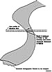
3-D![]() programs. The design procedure is diagrammed on Figure 1.
programs. The design procedure is diagrammed on Figure 1.
|
Narrow Targets and Stacking Bins
The horizontal resolution provided by a
The trace spacing in a given direction across a
As a general rule, there should be a minimum of three stacking bins – and preferably four bins – across the narrowest feature that needs to be resolved in a
For example, if the interpretation objective is to image meandering channels that are as narrow as 100 meters, then stacking bins should have lateral dimensions of approximately 25 meters or less
Source and Receiver Station Spacings
Geophysical texts show that the dimension of a
Thus, when a choice is made about the narrowest target that must be imaged, not only have the dimensions of stacking bins been determined, but source-station and receiver-station spacings also are defined.
Because of the 2-to-1 ratio between station spacings and stacking-bin dimensions, source-station and receiver-station spacings should be one-half (or less) of the narrowest horizontal dimension that needs to be interpreted from
Referring to Figure 1, we have now defined parameters – source-station and receiver-station spacings – required for the first calculation step of the
One appeal of the
Copyright © AAPG. Serial rights given by author. For all other rights contact author directly. |