PSSubmarine Mass Transport Complex Evolution and Control on Overlying Reservoir Deposition, Permian Cutoff Formation, West Texas*
By
Robert Amerman1, Eric P. Nelson1, Michael H. Gardner2, and Bruce Trudgill1
Search and Discovery Article #40194 (2006)
Posted May 19, 2006
*Adapted from poster presentation at AAPG Annual Convention, Houston, Texas, April 10-12, 2006.
Click to view posters in PDF format.
1Colorado School of Mines, Department of Geology and Geological Engineering; Golden Colorado ([email protected])
2Montana State University, Department of Earth Sciences, Bozeman, Montana
Abstract
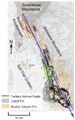
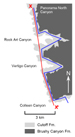
The Williams Ranch Member of the Cutoff Formation consists of six offlapping, basinward-stepping lithologic units of highstand carbonate turbidites deposited across a drowned Early Permian carbonate platform, then partially redistributed in slumps on the slope and basin floor. Slumps are intercalated with undeformed carbonate turbidites; the ratio of slumps to undeformed sediment increases basinward. Upslope evacuation scars correlate to downslope slump bodies. Gravity flow deposition and subsequent mass movement caused basinward thickening of the Williams Ranch Member and caused the toe of slope to shift basinward relative to the underlying Bone Spring Limestone. This shift controlled landward pinchouts of the overlying Permian Brushy Canyon Formation channel and sheet sandstone bodies. See Figures 1-1, 1-2, 1-3¸ 1-4, and 1-5.
Williams Ranch Member deposition both responded to and modified inherited bathymetric relief. Williams Ranch isopach thicks correspond to larger underlying lows and smaller overlying highs and exhibit a higher ratio of undeformed to slumped sediment and a higher percentage of soft-sediment folds relative to soft-sediment truncation surfaces. These slump “pile-ups” appear to be concentrated in inherited lows. Slump bodies show a general southward transport vector, with significant local variation possibly reflecting underlying bathymetric influence. With repeated slump events, “pile-up” zones resulted in local positive bathymetry. Brushy Canyon sand fairways and ponded sheets are focused in bathymetric lows, and sands are sidelapped against highs atop the Williams Ranch Member. Increased understanding of mass transport complex evolution may lead to better prediction of overlying reservoir geometry, both within the Brushy Canyon Formation and in analogous reservoirs in other deepwater settings.
Research Questions
1) Can deformed Cutoff units in the southern Guadalupe and northern Delaware Mountains be correlated with the three formal members and five informal correlation units of Harris (1982b; 1987; 1988a; 1988b; 2000)?
2) Can a sequence stratigraphic framework be established for the Cutoff that correlates to work by Fitchen (1993; 1997), Kerans and others (1992; 1993), Kerans and Fitchen (1995), Sarg (1986; 1989), Rossen and others (1988), Sarg and Lehmann (1986a; 1986b), Sonnenfeld (1993) and Sonnenfeld and Cross (1993) on equivalent shelfal units?
3) How many mass transport events (MTEs) are represented in the Cutoff?
4) What were the MTE transport vectors?
5) How far did the MTE bodies (bodies of sediment transported to their present locations, each in a single MTE) travel?
6) Does the nature of the MTEs evolve over time?
7) Do contractional and/or extensional domains exist, and where are they located?
8) How do microscale (mms-cms) features relate to mesoscale (ms) and macroscale (100s ms-kms) features?
9) How does the thickness of the mass transport complex (MTC) vary within the basin?
10) How did the Cutoff Formation influence development of paleo-bathymetry below the Brushy Canyon Formation?
11) How can internal Cutoff Formation structure be used to predict paleo-bathymetry below the Brushy Canyon Formation?
|
|
Soft-Sediment Structures
Zones of Abundant Microstructures (ZAMs) (Figure 2-1) A zone of abundant microstructures (ZAM) is a body of rock that contains up to four types of soft-sediment deformation features: 1) normal microfaults (NMF), 2) microboudins (MB), 3) reverse microfaults (RMF), and 4) microfolds (MF). Faults die out vertically within beds or sole into a hemipelagic layer. NMFs are generally listric. Fault length is limited by bed thickness (generally < 10 cm). Fold amplitudes are generally less than 1 cm. NMF and MB are usually overprinted by MF and/or RMF. This suggests that the slump was overprinted by contractional features when the downslope end of the body came to rest before the upslope end (Farrell, 1984). ZAMs are bounded on the top and bottom by truncation surfaces (TS) and may contain internal truncation surfaces as well. The vertical distance between bounding TS is no more than a few meters (the thickest ZAM observed is 6.5 m in height). ZAMs appear locally within Unit 7 and comprise most of the observed portion of Unit 9 in the Delaware Mountains. Bounding TS in Unit 9 are generally planar and have a shallow dip or are horizontal. Bounding TS within Unit 7 are often deformed themselves and may be part of larger mesoscopic folds or complex deformation zones (CDZ) that contain rocks without ZAMs. These relationships, and the relative thinness of Unit 9 and other ZAMs, suggest that: 1) ZAMs in Unit 7 were later transported piggyback style within larger slump bodies, and 2) Unit 9 represents a slump (or package of slumps) that was not later transported.
Complex Deformation Zones (CDZs) (Figures 2-2 and 2-3) Complex deformation zones are local 3D regions within a slump body that are 1) characterized by a set of fold segments that have axial surfaces with similar strikes and differing dips, and 2) roughly cylindrical in shape with the long axis generally horizontal. They occur within Units 7 and 8. Field evidence suggests that CDZs are concentrated within locally thicker zones within an MTE body and may indicate a soft-sediment "pile-up."
Structural Trends (Figures 2-4 and 2-5)
The orientation of fold axes in an MTE body may be an indicator of transport direction (roughly perpendicular to the fold axis), although there may be local variation within the body, and fold axes may rotate from the transport direction at body margins (Hansen, 1971). Lineations resulting from the intersection of normal microfaults and microfolds with bedding planes may also indicate transport direction at the times that extension and contraction were taking place, respectively. Fold axis orientations in the Cutoff Formation show variation by location and by correlation unit. The primary trend is N-S with a secondary trend of ENE-WSW. These two trends may represent: 1) differences in transport vectors among separate MTE bodies, or 2) deflection by underlying topography. Fold asymmetry may indicate the transport direction; however, relatively few measurable asymmetric folds were observed. The primary inferred direction from these folds is north to south, although some folds indicate the reverse. Unit 6 is excluded from this analysis as its nature in the Delaware Mountains is unclear.
Vertical Evolution of MTCThe vertical succession of MTE bodies in the Williams Ranch Member underwent an evolution over time. This evolution, from oldest to youngest, is as follows:
This pattern of waning size and/or deformation of MTE bodies occurs as the basin lowers its gradient through time (unit 6 is not considered as its nature in the Delaware Mountains is unclear).
Thickness Relationships (Figures 3-1, 3-2, and 3-3)
Isopach maps of the five correlation units suggest that:
Conclusions1) Deformed basinward Cutoff units were correlated with previously published undeformed shelfward units. Five basinward-stepping units were identified atop correlation unit 5 as part of the Williams Ranch Member (WRM). 2) A tentative second- and third-order sequence stratigraphic framework was established for the Cutoff that correlates to previous work on shelfal equivalents. 3) In the Delaware Mountains, at least 8 MTEs are represented in the WRM, not including earlier phases of multi-phase events. In the Guadalupe Mountains, MTEs were likely numerous, but their number is less well constrained. 4) Transport direction was primarily NNW to SSE with a secondary NE to SW component. 5) The three uppermost MTE bodies appear to be locally derived; the remainder may have been margin- or- slope-sourced, based on calculations using a power law relating runout and volume developed by Legros (2002). 6) MTE bodies within the WRM exhibit a pattern of waning volume and degree of deformation through time. 7) The dominant structural style is contractional, except north of Italy Canyon in the Guadalupe Mountains, where extensional evacuation scars coexist with scattered contractional features north of Italy Canyon. 8) CDZs and drape intervals are concentrated in areas of increased MTC thickness. ZAMs appear to result from local extension with later contractional overprinting. Some ZAMs appear to have been subjected to more than one phase of transport. 9) The WRM generally thickens basinward across the study areas through progradation and mass transport, with local variance resulting from preexisting topography and contractional “pile-ups.” 10) The WRM influenced development of paleo-bathymetry below the Brushy Canyon Formation (BCF) by filling preexisting larger-scale lows and creating smaller highs above them. Progradation and small-scale mass transport of the Cutoff shifted the toe of slope basinward from the inherited Victorio Peak toe of slope. The pinchout of the lower BCF coincides with the basinward limit of significant WRM mass transport deposits. 11) Internal Cutoff structure could potentially be used to predict paleo-bathymetry below the BCF. The highest percentage of CDZs and drape intervals is found within WRM thicks, filling preexisting lows and creating smaller local highs. The lowest percentage
ReferencesFarrell, S.G., 1984, A dislocation model applied to slump structures, Ainsa Basin, South Central Pyrenees: Journal of Structural Geology, v. 6, p. 727-736. Fitchen, W.M., 1993, Sequence stratigraphic framework of the upper San Andres Formation and equivalent basinal strata in the Brokeoff Mountains, Otero County, New Mexico, in D.W. Love, J.W. Hawley, B.S. Kues, J.W. Adams, G.S. Austin, and J.M. Barker, eds., Carlsbad region,New Mexico and West Texas, New Mexico Geological Society forty-fourth field conference, v. 44: Socorro, New Mexico, New Mexico Geological Society. Gardner, M.H., 2002, Slope and basin regional cross section, Brushy Canyon Formation, Delaware Mountains, west Texas: Unpublished. Hansen, E., 1971, Strain facies: New York, Springer-Verlag. Harris, M.T., 1982, Sedimentology of the Cutoff Formation (Permian), western Guadalupe Mountains, West Texas and New Mexico: Master‘s thesis, University of Wisconsin, Madison, Wisconsin, 186 p. Harris, M.T., 1987, Sedimentology of the Cutoff Formation (Permian), western Guadalupe Mountains, West Texas: New Mexico Geology, v. 9, p. 74-79. Harris, M.T., 1988a, Postscript on the Cutoff Formation: The regional perspective and some suggestions for nomenclature, in S.T. Reid, R.O. Bass, and P. Welch, eds., Guadalupe Mountains revisited; Texas and New Mexico, West Texas Geological Society Publication 88-84: Midland, Texas, West Texas Geological Society, p. 141-142. Harris, M.T., 1988b, Sedimentology of the Cutoff Formation (Permian), western Guadalupe Mountains, West Texas, in S.T. Reid, R.O. Bass, and P. Welch, eds., Guadalupe Mountains revisited; Texas and New Mexico, West Texas Geological Society Publication 88-84: Midland, TX, West Texas Geological Society, p. 133-140. Harris, M.T., 2000, Members for the Cutoff Formation, western escarpment of the Guadalupe Mountains, West Texas, in B.R. Wardlaw, R.E. Grant, and D.M. Rohr, eds., The Guadalupian symposium, Smithsonian contributions to the Earth sciences, 32: Washington, Smithsonian Institution Press, p. 101-120. Kerans, C., and W.M. Fitchen, 1995, Sequence hierarchy and facies architecture of a carbonate-ramp system: San Andres Formation of Algerita Escarpment and Western Guadalupe Mountains, West Texas and New Mexico, Report of Investigations No. 235, Bureau of Economic Geology, 86 p. Kerans, C., W.M. Fitchen, M.H. Gardner, M.D. Sonnenfeld, S.W. Tinker, and B.R. Wardlaw, 1992, Styles of sequence development within uppermost Leonardian through Guadalupian strata of the Guadalupe Mountains, Texas and New Mexico, in D. H. Mruk, and B. C. Curran, eds., Permian Basin exploration and production strategies: Applications of sequence stratigraphic and reservoir characterization concepts: West Texas Geological Society Publication 92-91: Midland, Texas, West Texas Geological Society, p. 1-6. Kerans, C., W.M. Fitchen, M.H. Gardner, and B.R. Wardlaw, 1993, A contribution to the evolving stratigraphic framework of Middle Permian strata of the Delaware Basin, Texas and New Mexico, in D. W. Love, J. W. Hawley, B. S. Kues, J. W. Adams, G. S. Austin, and J. M. Barker, eds., Carlsbad region, New Mexico and West Texas, New Mexico Geological Society forty-fourth annual field conference: Socorro, New Mexico, New Mexico Geological Society, p. 175-184. Kullman, A.J., 1999, Fracture networks and fault zone features in a deep water sandstone, Brushy Canyon Formation, West Texas: Master’s thesis, Colorado School of Mines, Golden, Colorado, 256 p. Lambert, L.L., 2000, The Guadalupian GSSP-The world standard Middle Permian series-Guadalupe Mountains National Park, in C.J. Crow, and G.L.J. Bell, eds., Field trip guidebook: Guadalupian deposition in sabkha, shelf, reef, and basin environments, Guadalupe Mountains, Texas and New Mexico, p. 57-70. Legros, F., 2002, The mobility of long-runout landslides: Engineering Geology, v. 63, p. 301-331. Rossen, C., P.J. Lehmann, and J.F. Sarg, 1988, Trail guide for Day 1: Shumard to Bone Canyon traverse, in J.F. Sarg, C. Rossen, P.J. Lehmann, and L.C. Pray, eds., Geologic guide to the western escarpment, Guadalupe Mountains, Texas: Permian Basin Section, SEPM publication 88-30: Tulsa, Oklahoma, Society of Economic Paleontologists and Mineralogists, p. 17-60. Sarg, J.F., 1986, Second day: Facies and stratigraphy of upper San Andres basin margin and lower Grayburg inner shelf, in G.E. Moore, and G.L. Wilde, eds., Lower and Middle Guadalupian facies, stratigraphy, and reservoir geometries: San Andres/Grayburg formations, Guadalupe Mountains, New Mexico and Texas: Permian Basin Section, SEPM Publication 86-25: Tulsa, Oklahoma, Permian Basin Section: Society of Economic Paleontologists & Mineralogists, p. 83-93. Sarg, J.F., and P.J. Lehmann, 1986a, First day: Facies and stratigraphy of lower-upper San Andres shelf crest and outer shelf and lower Grayburg inner shelf, in G.E. Moore, and G.L. Wilde, eds., Lower and Middle Guadalupian facies, stratigraphy, and reservoir geometries: San Andres/Grayburg formations, Guadalupe Mountains, New Mexico and Texas: Permian Basin Section SEPM Publication 86-25: Tulsa, Oklahoma, Permian Basin Section: Society of Economic Paleontologists & Mineralogists, p. 9-35. Sarg, J.F., and P.J. Lehmann, 1986b, Lower-middle Guadalupian facies and stratigraphy: San Andres/Grayburg formations, Permian Basin, Guadalupe Mountains, New Mexico, in G.E. Moore, and G.L. Wilde, eds., Lower and Middle Guadalupian facies, stratigraphy, and reservoir geometries: San Andres/Grayburg formations, Guadalupe Mountains, New Mexico and Texas: Permian Basin Section, SEPM Publication 86-25: Tulsa, Oklahoma, Permian Basin Section: Society of Economic Paleontologists & Mineralogists, p. 1-8. Slope and Basin Consortium, 2003, Geologic map of Permian strata in the Delaware Mountains, west Texas: Unpublished. Slope and Basin Consortium, 2004, Photograph of western escarpment of the Guadalupe Mountains, west Texas: Unpublished. Sonnenfeld, M.D., 1993, Anatomy of offlap: Upper San Andres Formation (Permian, Guadalupian), Last Chance Canyon, Guadalupe Mountains, New Mexico, in D.W. Love, J.W. Hawley, B.S. Kues, J.W. Adams, G.S. Austin, and J.M. Barker, eds., Carlsbad region, New Mexico and West Texas, New Mexico Geological Society forty-fourth annual field conference: Socorro, New Mexico, New Mexico Geological Society, p. 195-203. Sonnenfeld, M.D., and T.A. Cross, 1993, Volumetric partitioning and facies differentiation within the Permian upper San Andres Formation of Last Chance Canyon, Guadalupe Mountains, New Mexico, in R.G. Loucks, and J.F. Sarg, eds., Carbonate sequence stratigraphy-Recent developments and applications: American Association of Petroleum Geologists Memoir 57, p. 435-474.
Ongoing ResearchImmediate research goals include:
Land access issues have prevented continuing work in the Delaware Mountains, but planned future research there includes completion of mapping and collection of additional structural and thickness data, as well as extension of the study to include outcrops to the north and south and the Cutoff units below the Williams Ranch. |