Click to view the posters in PDF
PSSeal and Reservoir Characterization of Upper Slope Fan Lithofacies:
Example of High-Frequency Variability
By
William C. Dawson1, William R. Almon1, and S.J. Johansen2
Search and Discovery Article #40124 (2004)
*Adapted from poster presentation at AAPG Annual Meeting, Dallas, Texas, April 18-21, 2004; closely related poster/article, prepared and presented by Wm. R. Almon and Wm. C. Dawson, is entitled "Seal Character and Variability Within Deep-Marine Depositional Systems: Seal Quantification and Prediction" (Search and Discovery Article #40125).
1ChevronTexaco, Bellaire, TX ( [email protected] ; [email protected])
2Ameriven, Venezuela
Abstract
Conventional cores of a lowstand sequence (interpreted as a slope fan) reveal fine-scale variability within potential seal and reservoir units and provide insights concerning depositional process, sedimentation rates, and stratigraphic compartmentalization, which are below wire-line log and seismic resolution. The lower cored interval consists of dark gray to black foraminiferal shale representing slow (hemipelagic to hemi-turbiditic) deposition during a highstand. This maximum flooding shale is a major correlation marker because of its distinct gamma ray signature; it has an erosional upper contact (sequence boundary). This erosional contact is overlain by stacked, fining-upward stratal packages consisting of: deformed, argillaceous, fine-grained sandstones; sandy mudstones; and very silty gray shales. The sand-prone units consist of thinly interstratified shale, siltstone, and sandstone interpreted as blocks of levee deposits that probably slumped into channels. The interstratified sandy mudstones represent thin debris flows. Compartmentalization by numerous shale laminations and clay smears (along micro-faults) is conspicuous. The character of this argillaceous slope-fan reservoir is interpreted as poor (< 10% porosity). Results of high-pressure mercury capillary injection analysis reveal excellent seal character (10% nonwetting saturation > 10,000 psia) is exhibited by these shales below the sequence boundary. In contrast, silty shales and argillaceous siltstones from the overlying lowstand units have moderate to poor seal potential. Seal character is related to shale texture and fabric, content of detrital silt, early marine diagenesis (carbonate cementation), and stratigraphic position. These data provide a compelling argument for textural control of seal character induced by high-frequency sedimentary cycles.
|
uAbstract
uAbstract
uAbstract
uAbstract
uAbstract
uAbstract
uAbstract
uAbstract
uAbstract
uAbstract
|
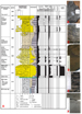
Introduction(Figures 1,2-1, 1,2-2, and 1,2-3)
Several important discoveries have been made in channelized slope fans along the margin of West Africa and other deepwater basins (Weimer et al., 2000; Prather, 2003). Seismic elements isolated from within these muddy slope packages commonly exhibit sinuous patterns on plan-view maps (Kolla et al., 2001; and Fonnesu, 2003). In offshore Angola, and elsewhere, these sinuous features are interpreted as migrating deep marine channels that acted as conduits for turbidity flows (e.g., Sinclair and Tomasso, 2002). High-resolution data (wire-line logs and cores) reveal very complex association of lithofacies within this depositional setting. Considerable by-passed oil (~30% OOIP) can be trapped in thin-bedded channel-margin lithofacies (Weimer et al., 2000). Recognition of shale occurrences, bed thickness and geometries, and variations in net-to-gross are major issues related to maximizing hydrocarbon recovery from fine- to very fine-grained, channel-margin reservoirs and associated channel-levee units. In particular, slumping, small-scale faulting, and the presence of mud drapes reduce intra-reservoir connectivity and lower recovery efficiency. Furthermore, facies-influenced diagenesis can induce variations in reservoir character.
Core Descriptions
General StatementFine-scale variability in lithofacies and reservoir character is not evident from seismic data. Detailed (foot-by-foot) comparison of cores and wire-line log curves is critical to the development of reservoir models. This sub-seismic variability may control the economic viability of a prospect.
8035 to 8057 feet Lithology: Yellowish-orange, fine-grained sandstones, interstratified with dark gray shales, argillaceous siltstones, and pebbly mudstones. Convoluted bedding is developed throughout. Wire-line log character: GR curve has an irregular profile reflecting thin alteration of shales and sandstones with values ranging from 30 to 80 AMP units. Resistivity log compromised by washout and caving of bore hole. Interpretation: Lowstand systems tract (slope fan depositional system). Probable abandonment channel filled with slumped channel-levee blocks and debris flow lags.
8057 to 8068.4 feet Lithology: Moderate dark gray to grayish black noncalcareous shales. Sub-fissile with scattered lenses of siltstone. Bedding ranges from planar to convoluted. Wire-line log character: Slightly elevated GR (~ 90 API units) with low resistivity values (1.2 to 2 ohms). Interpretation: Minor condensed interval separating two stacked channel-levee units or shale-filled channel (abandoned channel).
8068.4 to 8105.25 feet Lithology: Complex of thinly interstratified oil-stained, yellowish-gray, fine-grained sandstones, argillaceous siltstones, dark gray shales, and pebbly mudstones. Exhibits syndepositional deformation (convoluted laminae) and microfaulting. Wire-line log character: GR ranges from 20 to 85 API units (fining upward). Resistivity readings vary between 2.5 (siltstones) and 45 ohms (oil-bearing sandstones). Interpretation: Lowstand systems tract (slope-fan depositional setting). Probable abandoned channel filled with slumps (levee-derived) and debris flows.
8105.25 to 8117.5 feet Lithology: Grayish black to brownish black shales. Less calcareous than underlying unit. Sub-fissile with moderately developed laminations. Wire-line log character: Modest resistivity (~ 25 ohms) with depressed sonic (100 to 110 ms/ft). Exhibits prominent GR spike (160 to 175 API units). Interpretation: Highstand systems tract or initial falling stage systems tract.
8117.5 to 8123 feet Lithology: Grayish black, calcareous and pyritic shale. Exhibits blocky fracture and faint laminations (accentuated by concentrations of foraminifer tests). Wire-line log character: High GR (130 to 150 API units); elevated resistivity (> 40 ohms). Interpretation: Maximum flooding shale.
Angola Seal Data(Figures 4-1, 4-2, 4-3, 4-4, 4-5, 4-6, 4-7, and 4-8)
Our seal analyses reveal the common presence of six recurring shale types in deepwater depositional settings. Shale types 1, 2, and 6 exhibit excellent top (membrane) seal potential. Silt-rich shales (types 3, 4, and 5) have considerably lower seal capacity. Shapes of mercury-injection curves (MICP analysis) allow the recognition of three classes of pore structure (i.e., seal types). Silt-rich samples (type 4) have relatively low injection pressures. In contrast, carbonate-cemented silt-poor samples (type 2) have injection pressures that exceed 1000 psia. Type 3 samples have intermediate injection pressures. Each shale type occupies a particular stratigraphic position. Type 2 shales represent upper transgressive and condensed intervals. Type 3 shales occur in middle to lower parts of transgressive units, and very silty (type 4) shales represent lowstand and highstand stratal packages.
Seal Stratigraphy
This core penetrated stacked submarine channels, which are encased in marine shales. Our data show clearly that shale facies and variations in shale fabric are important factors in determining seal competency. Shale facies and seal capacity vary within the context of sequence stratigraphy. The underlying fossiliferous black shale has exceptional seal character, and the overlying dark gray fissile shale (probable condensed interval) exhibits excellent seal potential. The sequence boundary at 8105 ft is a significant pressure barrier. These marine shales are expected to have lateral continuity exceeding that of the channelized sandstone units.
Reservoir Character(Figures 6-1, 6-2, 6-3, 6-4, 6-5, 6-6, 6-7, 6-8, 6-9, 6-10, 6-11, 6-12, and 6-13)
Petrographic analysis and Touchstone (porosity-depth) modeling show these fine- and medium-grained sandstones respond differently to burial diagenesis. Porosity and permeability of fine-grained (channel-margin) lithofacies are consistently lower at a given burial depth relative to medium-grained (channel-axis) lithofacies. Also, finer grained lithofacies are more susceptible to intergranular cementation by syntaxial quartz during burial diagenesis.
Summary and ConclusionsSeal character in slope-fan settings is related to variations of shale fabric and texture (e.g., content of detrital silt). At least three distinctive shale microfacies, each having different MICP (seal) profiles are present in the cored interval. · Top seal potential ranges from moderate to excellent (in the absence of fractures). · Lateral seal potential ranges from moderate to poor.
Variations in depositional fabric, which correlate with high-frequency (wire-line log-scale) stratigraphic fluctuations, are responsible for observed variations in seal capacity. Reservoir compartmentalization, induced by shale laminae and clay smears (micro-faults), is a common aspect of channel-margin lithofacies within this deep-marine (slope-fan) depositional system. Hemipelagic shales and argillaceous debris flows also compartmentalize the studied LST reservoir interval. Reservoir character (especially permeability) is compromised by ductile folding and small-scale faulting. Slumping along with the deposition of mud drapes contribute to limited internal connectivity in channel-margin lithofacies. Porosity-depth modeling suggests that the reservoir potential of fine-grained channel-margin lithofacies degrades more rapidly during burial relative to coarser channel-axis lithofacies.
ReferencesAlmon, W.R., Dawson, Wm. C., Sutton, S.J., Ethridge, F.G., and Castelblanco, B., 2002, Sequence stratigraphy, facies variation and petrophysical properties in deepwater shales, Upper Cretaceous Lewis Shale, south-central Wyoming: GCAGS Transactions, v. 52, p. 1041-1053. Dawson, Wm. C., and Almon, W.R., 2002, Top seal potential of Tertiary deepwater Gulf of Mexico shales: GCAGS Transactions, v. 52, p. 167-176. Fonnesu, F., 2003, 3D seismic images of a low-sinuosity slope channel and related depositional lobe (West Africa deep-offshore): Marine and Petroleum Geology, v. 20, p. 615-629. Galloway, 1998, Siliciclastic slope and base-of-slope depositional system: Component facies, stratigraphic architecture, and classification: AAPG Bulletin, p. 569-595. Jennings, J.J., 1987, Capillary pressure techniques: application to exploration and development geology: AAPG Bulletin, v. 71 (10), p. 1196-1209. Kolla, V., Bourges, P., Urruty, J.M., and Safa, P., 2001. Evolution of deep-water Tertiary sinuous channels offshore Angola (west Africa) and implications for reservoir architecture: AAPG Bulletin, v. 85 (8), p. 1373-1405. Prather, B.E., 2003, Controls on reservoir distribution, architecture and stratigraphic trapping in slope settings: Marine and Petroleum Geology, v. 20, p. 529-545. Prather, B.E., Booth, J.R., Steffens, G.S., and Craig, P.A., 1998, Classification, lithologic calibration and stratigraphic succession of seismic facies from intraslope basins, deep water Gulf of Mexico, USA: AAPG Bulletin, v. 82 (5), p. 701-728. Sinclair, H.D., and Tomasso, M., 2002, Depositional evolution of confined turbidite basins: Journal Sedimentary Research, v. 72 (4), p. 451-456. Weimer, P., Slatt, R.M., Dromgoole, P., Bowman, M., and Leonard, A., 2000, Developing and managing turbidite reservoirs: case histories and experiences: results of the 1998 EAGE/AAPG Research Conference: AAPG Bulletin, v. 84, p. 453-465.
AcknowledgementsWe thank ChevronTexaco for granting permission to present these data and interpretations. W.T. Lawrence prepared thin sections and assisted with core photography. J.L. Jones provided SEM images, and D.K. McCarty completed XRD analyses. Poro-Technology, Houston, TX conducted MICP analyses. Graphic design by L.K. Lovell.
|