![]() Click to view article in PDF format.
Click to view article in PDF format.
Naturally Underpressured Reservoirs: Applying the Compartment Concept to the Safe Disposal of Liquid Waste*
By
Jim Puckette1 and Zuhair Al-Shaieb1
Search and Discovery Article #40071 (2003)
*Online adaptation of presentation at AAPG Southwest Section Meeting, Fort Worth, TX, March, 2003 (www.southwestsection.org)
1School of Geology, Oklahoma State University, Stillwater, OK 74078 ( [email protected] ) ( [email protected] )
The Oklahoma Panhandle region contains abnormally low-pressure reservoirs that are isolated from the shallow hydrostatic domain and overpressured reservoirs in the deep Anadarko basin. These underpressured reservoirs, which can be identified and mapped using available petroleum industry data, are potential repositories for liquid waste. They contain naturally low pore-fluid pressures and are completely sealed by thick confining units. Many of these compartments contain oil and gas. Fluid withdrawal during production has further reduced reservoir pressures, facilitating disposal by lowering injection and displacement pressures.
Types and sizes of compartments were strongly influenced by depositional environment. Individual channel-filling sandstones within valley-fill sequences form small-compartments, whereas sandstone reservoirs formed from sediments reworked during marine transgressions became large ones. Within the carbonate domain, thick accumulations of grain-rich sediment, subsequently altered by dissolution and/or dolomitization, form large- to regional-sized compartments. Selected sandstone and carbonate reservoirs have calculated disposal volumes ranging from approximately 0.5 million barrels to 21 million barrels per well.
Compartmentalized reservoirs with abnormally low fluid pressures offer an intriguing alternative for liquid waste disposal. They exist as self-contained vessels whose seals have confined pore-fluid pressures for durations of geologic time. Seal longevity and integrity are evidenced by the very existence of naturally occurring subnormal pressures that did not equalize with the normally pressured hydrostatic environment. These reservoirs, by virtue of their compartmentalized nature, fulfill two critical criteria for safe liquid waste disposal, (1) non-migration and (2) total isolation from the sphere of human activities.
Naturally underpressured reservoir compartments offer an intriguing option for the safe disposal of liquid wastes. Pore pressures in underpressured reservoirs are often lower than the hydrostatic pressure generated by a column of freshwater. Compartmentalized reservoirs in sedimentary basins, by virtue of their three-dimensional sealing, meet two critical criteria concerning the confinement of liquid toxic waste, (1) isolation from the surficial environment and (2) non-migration.
Abnormally low fluid pressure is evidence that a proposed injection zone is a compartment and isolated from its surroundings. In contrast, near-normal pressure suggests that the reservoir is part of a larger hydrostatic or hydrodynamic system. Fluid type is equally important. Underpressured oil- and gas-bearing compartments, especially pressure-depleted ones, have injection and displacement pressures that are much lower than water-filled, normally pressured reservoirs.
Pressure data provided by the oil and gas industry are used to demonstrate that naturally underpressured reservoir compartments are common in the Oklahoma and Texas Panhandle area of the Southern Midcontinent region. These compartments, which often contain pressures that are further reduced by oil and gas production, are potential repositories for injected liquid waste.
|
uUnderpressured disposal zones uIntermediate-size compartment
uUnderpressured disposal zones uIntermediate-size compartment
uUnderpressured disposal zones uIntermediate-size compartment
uUnderpressured disposal zones uIntermediate-size compartment
uUnderpressured disposal zones uIntermediate-size compartment
uUnderpressured disposal zones uIntermediate-size compartment
uUnderpressured disposal zones uIntermediate-size compartment
uUnderpressured disposal zones uIntermediate-size compartment
uUnderpressured disposal zones uIntermediate-size compartment
|
Disposal Zones and the Compartment Concept The discovery of abnormally pressured fluid in deep basins altered the conventional interpretation of basin fluid flow. Abnormal reservoir pressures are either greater or less than normal hydrostatic pressure for a given depth. A normal hydrostatic gradient is the pressure generated by an essentially static column of water that extends from reservoir depth to the surface. The resulting maximum pressure gradient is vertical and attributable to the weight (gravity x density) of the overlying fluid column (Dahlberg, 1995). Since fluids at depth in basins generally are saline, a brine from the Gulf Coast basin with a gradient of 0.465 psi/ft. became the petroleum industry standard for a normal hydrostatic gradient (Stuart, 1970; Bradley, 1975). Abnormal fluid pressure for a given depth will plot either higher or lower than the benchmark gradient. Abnormally high pressure (overpressure) was initially recognized in the Gulf Coast basin. This was followed by the revelation that abnormally low pressure (underpressure) existed. Bradley (1975) proposed that abnormal fluid pressures are isolated from their surroundings by seals. These seals prevent abnormal pressures, which may deviate widely from the hydrostatic pressure, from equalizing with the normally pressured (hydrostatic/hydrodynamic) environment. Bradley and Powley (1994; 1987) presented evidence that sedimentary basins are typically divided into a network of compartments that are isolated by sealing rocks. Compartments are highly variable in size, ranging from less than 1 mi2 (2.6 km2) to tens or hundreds of mi2 in areal extent. Individual compartments are recognized by their fluid pressures, which are distinctly different from pressures in adjacent compartments or non-compartmentalized (hydrostatic/hydrodynamic) reservoirs. Large fluid compartments situated well below the base of fresh water (outside the sphere of human activity) and located in geologically stable areas may be ideal repositories for toxic liquid wastes. Furthermore, if these compartments are underpressured relative to fluid pressures in strata positioned above and below, leaks or punctures in the enclosing seals would result in an initial net inflow of fluid into the compartment, thereby preventing the escape of waste.
Compartmentalization of Western Oklahoma and the Texas Panhandle The subsurface rock column in western Oklahoma and the Texas Panhandle is compartmentalized and divided into distinct pressure domains (Al-Shaieb and others, 1994a; 1994b). Within the Anadarko basin (Figure 1), three general fluid-pressure domains are recognized: (1) shallow normal pressure, (2) overpressure that extends from a depth of approximately 10,000 ft to the Woodford Shale, and (3) deep normal pressure below the Woodford Shale in carbonates of the Hunton and Arbuckle Groups (Figure 1). This pressure stratification clearly demonstrates that fluid pressures do not continuously increase with depth and that seals separate these diverse pressure domains. Similarly stratified pressure intervals exist in deep basins worldwide (Powley, 1990). The significance of seals is illustrated by the change in pressure values within the Morrowan interval across western Oklahoma. Morrowan reservoirs in the deep Anadarko basin have abnormally high pore-fluid pressures that approach lithostatic values (Al-Shaieb and others 1992; 1994a). In contrast, Morrowan pore-fluid pressures in the Oklahoma Panhandle are often less than one half of the hydrostatic value (Puckette, 1996). A pressure-depth gradient map and generalized potentiometric surface diagram (Figures 2 and 3) illustrate this regional change in pressure.
Stratigraphy and Pressure Architecture in the Oklahoma Panhandle Region The Oklahoma Panhandle region contains underpressured, compartmentalized reservoirs. They were identified using some two thousand measurements of reservoir pressure collected mostly from oil and gas industry sources. These include direct measurements from drill-stem tests and other downhole sources and calculated values from wellhead shut-in pressures. The reliability of petroleum industry data was established by calculating a correlation coefficient between pressure values acquired from two separate sources, (1) drill-stem tests and (2) static initial wellhead shut-in pressures (IWHSIP). The results (Pierson r=0.9834) indicate that for high-permeability reservoirs, calculated pressures from IWHSIP closely matched those of drill-stem tests (Puckette, 1996). Pressure-depth profiles and potentiometric surface maps illustrate a significant vertical differentiation in pressure across the stratigraphic column in the Oklahoma Panhandle. In the western Panhandle near the Keyes Dome (Figure 4), six separate groupings or domains are recognized. They are separated by relatively flat-lying stratigraphic seals that correlate to evaporite or shale beds (Figure 5). Six regional seal zones subdivide the rock column in the panhandle region (Figure 5). Descending, the first seal occurs below the base of freshwater and separates it from gas- and brine-bearing reservoirs in the Tubb and Red Cave intervals. Important, low-permeability beds in this seal include the shale-rich Cloud Chief Formation, Whitehorse Group and Dog Creek Shale, the Blaine Gypsum, the shale- and salt- dominated Hennessey Shale and Cimarron Anhydrite (Figure 5). The second seal includes the lower part of the Hennessey Shale and the evaporite-rich Wellington Formation. This seal separates Tubb and Red Cave reservoirs from those in the underlying Chase and Council Grove Groups. The third seal zone is the shale-dominated interval below the Council Grove Group. It separates Permian-age Council Grove and Chase Group reservoirs from those in the deeper Pennsylvanian Virgilian and Missourian Series. The fourth regional seal separates Pennsylvanian Missourian and Desmoinesian reservoirs from those in the Morrowan interval. This seal coincides with the Desmoinesian ‘Cherokee’ and Atokan shales. Seal five is the upper Morrowan shale. It isolates upper Morrowan sandstone reservoirs from lower Morrowan and Mississippian Chesterian ones. The sixth seal (not shown on Figure 5) separates the lower Morrowan/Chesterian interval from reservoirs in the Ordovician Simpson Group and the Cambro-Ordovician Arbuckle Group. The shallowest pressure domain is near surface and associated with freshwater aquifers, including the Ogallala. This shallow hydrostatic domain extends to the Blaine Anhydrite/Gypsum (Figures 4 and 5). Pre-irrigation potentiometric surfaces in the fresh water aquifer approached or intersected the surface (Schoff and Stovall, 1943). The original pressure-depth gradient in the freshwater system (0.433 psi/ft) is reduced as a result of lowering of the water table (potentiometric surface) by irrigation. The second pressure domain starts beneath the Blaine seal and extends downward to the Wellington seal. Reservoirs in this interval have pressure-depth gradient values around 0.24 psi/ft (Figure 4) and potentiometric surfaces close to 2500 ft (760 m) above sea level. The third important pressure domain includes reservoirs of the Permian Chase Group that are located below the Wellington seal interval. In the Keyes area, these reservoirs have pressure-depth gradients around 0.15 psi/ft and potentiometric surfaces around 700 ft (210 m) above sea level. The highest-pressure values recorded in pre-Permian rocks are found in the Pennsylvanian upper Morrowan reservoirs. Upper Morrowan (Purdy) sandstone reservoirs have pressure-depth values that range from 0.25 to 0.29 psi/ft and a maximum potentiometric surface around 2600 ft (790 m). This value is still well below the average surface elevation of 3300 ft (1000 m). These Purdy values are considerably higher than pressure-depth gradient values of 0.20 and potentiometric surfaces of 1500 ft (460 m) measured for the underlying lower Morrowan (Keyes) sandstone and Mississippian reservoirs. The Keyes Sandstone is separated from the Purdy Sandstone by a shale seal. Pressure regimes below the Mississippian are not well defined, but pressure measurements from deeper Arbuckle reservoirs in the region suggest a return to near-hydrostatic pressure with depth.
Compartmentalization is apparent when distinct pressure measurements or fluid types indicate reservoir separation and isolation. Al-Shaieb et al (2002, 1994; 1992) documented compartmentalization of the Anadarko basin and the intrastratal changes in Morrowan pressure regimes from the deep basin to shelf regions. This change from extreme overpressure in the deep basin, to underpressure in the panhandle (Figures 2 and 3), is evidence of the regional compartmentalization and sealing that prevented the equilibration of Morrowan pressures over geologic time. Localized compartmentalization of the Morrow (an operational term for Morrowan) is evident in the panhandle. In the Keyes area, lower Morrow Keyes sandstone and Mississippian Chester (operational term for Chesterian) reservoirs have pressure-depth gradients around 0.2 psi/ft, whereas those in the upper Morrow ‘Purdy’ sandstone are 0.25 psi/ft (Figure 4). In contrast, pressure measurements from Beaver County indicate Keyes and Chester p-d gradients have increased to around 0.28 psi/ft and 0.36 psi/ft respectively, whereas upper Morrow gradients remained around 0.23 to 0.25 psi/ft. Consequently, upper Morrow reservoirs, which were the highest-pressured in the Keyes area, have the lowest p-d gradients in the Beaver area (Figure 6). This switch in relative pressure is evidence that the Purdy and Keyes/Chester reservoirs are independent fluid-pressure systems, isolated by seals. Sealed, three-dimensionally isolated pressure compartments offer a naturally occurring system that fits the no-migration criterion of an ideal disposal zone. Within the Oklahoma Panhandle region, example compartments were classified by type and size and systematically evaluated as potential disposal sites.
Potential Underpressured Disposal Zones Several underpressured reservoirs were characterized for geologic suitability as disposal zones. Specific criteria considered included porosity and permeability, thickness and areal extent, and confining seals. Porosity measurements were taken from wire-line logs, thin-section petrography, and the literature. Thickness and areal extent were established by mapping. Fluid types and pressure measurements were used to confirm compartment boundaries. The integrity of confining units was evaluated by determining their lithology, thickness, and distribution. Seal continuity was evaluated by examining the site area for faults or factures that could transect confining units and become conduits for migration. Compartments were classified by host lithology and size. Once classified as carbonate or siliciclastic, compartments were subdivided based on the volume of liquid petroleum or equivalent volume of gas they had produced. Types and sizes of compartments were strongly influenced by depositional environment. Individual channel-filling sandstones within valley-fill sequences form small compartments. On the other hand, sandstone bodies formed from sediments that were reworked and redistributed during marine transgression became large compartments. Within the carbonate domain, thick accumulations of grain-rich sediments that were subsequently dissolved and/or dolomitized form large, even regional compartments. In contrast, those formed from thin, grain-rich shoals in heterolithic assemblages are small.
Sandstone Example: Large Compartment The lower Morrowan Keyes sandstone in Keyes field, Cimarron and Texas Counties Oklahoma is used to illustrate a potential large siliciclastic disposal zone. The sandstone forms thicker trends in valleys on the eroded Mississippian topography and sheet-like deposits as a result of reworking during a marine transgression. Sandstone thickness is highly variable and net reservoir may be absent in intervalley areas. Thickness maps were used to determine trends and thickness of the Keyes reservoir. The net sandstone thickness map (Figure 7) delineates thicker sand accumulations along the paleodrainage system. Net reservoir was defined as sandstone with positive filtercake accumulation, spontaneous potential (sp) deflection of >60 millivolts, density porosity >10%, and/or positive separation between microresistivity curves (Figure 8). Maximum reservoir thickness exceeds 100 ft (30 m) in paleovalleys. Porosity in the Keyes Sandstone is mostly secondary and resulted from dissolution of labile grains (Puckette, 1996; Gerken, 1992). Average porosity is approximately 15% and highly variable, primarily as a result of carbonate cement. Reported average permeability values range from 58 md to 100 md (Kansas Geological Survey, 1959; Stevens, 1960). Reservoir or injection capacity is calculated using a volumetric equation that considers reservoir parameters, fluid properties and temperature (Bradley, 1985). An ideal site for injection into the Keyes reservoir is the thick valley fill sandstone trend in the central part of T.5N., R.9ECM. Using a conservative thickness (h) of 50 ft (14 m), 640 acre area (A), 15% porosity (f), 0.35 water saturation, and an increase in reservoir pressure from 100 psi to 800 psi, a Keyes disposal zone could accept approximately 21 million barrels of liquid without exceeding original reservoir pressure.
Sandstone Example: Intermediate-Size Compartment The NE Rice field in T.3N., R.10ECM, Texas County Oklahoma, is used to illustrate an intermediate size reservoir compartment confined within an incised valley. The distribution and geometry of the ‘lower’ Purdy sandstone are shown in a map (Figure 9) and cross section (Figure 10) from Harrison (1990). Production data suggest the ‘lower’ Purdy is a common reservoir throughout the field. The reservoir is confined along the valley axis by low-permeability, clay-rich valley fill and laterally by clay-rich valley fill or the valley walls. Porosity values in the ‘lower’ Purdy sandstone range from 8 to 25% and average 21% (Harrison, 1990). Williams (1961) reported that typical permeability in the ‘lower’ Purdy sandstone was 557 md. Net reservoir was defined as sandstone with positive filtercake accumulation, spontaneous potential (sp) deflection of >60 millivolts, density porosity >10%, and gamma-ray values of <75 API units. Maximum reservoir thickness exceeds 10 m (30 ft). The ‘lower’ Purdy sandstone in NE Rice field is primarily an oil reservoir with a narrow gas cap located along its updip margin. It also contains water along the eastern boundary. Using a 40 acre area (A), an average reservoir thickness of 20 ft (6 m), 15% porosity (f), 35% water saturation, and an increase in reservoir pressure from 250 psi to 1300 psi, a ‘lower’ Purdy disposal zone could accept approximately 480 thousand barrels of liquid waste. The total encasement of valley fill sandstones in drilling-defined low permeability clay-rich rocks may make these sandstones ideal repositories for extremely toxic liquid waste. Though these reservoirs are volumetrically smaller than other types, their well-defined three-dimensional confinement ensures their fulfilling the no-migration criterion of an ideal disposal zone. Compartmentalized reservoirs with abnormally low fluid pressures offer an intriguing alternative for liquid waste disposal. They exist as self-contained vessels whose seals have confined pore-fluid pressures for durations of geologic time. Seal longevity and integrity are evidenced by the existence of abnormally low pressures that have not equalized with the hydrostatic environment. The underpressured compartmentalized reservoirs discussed in this paper have different capacities, but these common features: 1. Original pore-fluid pressures that were less than those in deeper and shallower strata, and considerably lower than normal pressure, 2. Mappable, three-dimensionally isolated or compartmentalized geometry, 3. Thick confining beds that are not folded or offset by transecting faults, and 4. Pore-fluid pressures that are reduced by oil and gas production, resulting in lower injection and displacement pressures. These naturally underpressured reservoirs meet the no-migration criterion of an ideal liquid waste disposal zone. Their confining beds should remain intact as long as they are not repressured above original (pre-production) natural values. In addition, example reservoirs are delineated by oil and gas boreholes that could be converted to monitoring wells, thereby ensuring proper pressure maintenance. Depleted gas-bearing compartments in tectonically stable areas such as the Oklahoma Panhandle region could provide safe storage sites that remain confined for tens of millions of years.
REFERENCESAl-Shaieb, Z., Puckette, J., and Close, A., 2002, Seal characterization and fluid-inclusion stratigraphy of the Anadarko basin, in Cardott, B. J. (ed.), Revisiting old and assessing new petroleum plays in the southern Midcontinent, Oklahoma Geological Survey Circular 107, p. 153-161. Al-Shaieb, Z., J. Puckette, P. Ely, and V. Tigert, 1992, Pressure compartments and seals in the Anadarko basin, in Johnson, K. S., and Cardott, B. J. (eds.), Source Rocks in the Southern Midcontinent, Oklahoma Geological Survey Circular 93, p. 210-228. Al-Shaieb, Z., J. Puckette, A. A. Abdalla, and P. Ely, 1994a, Mega compartment complex in the Anadarko basin: a completely sealed overpressured phenomenon, in Ortoleva, P. J. (ed.) Basin compartments and Seals: American Association of Petroleum Geologists Memoir 61, p. 55-68. Al-Shaieb, Z., J. Puckette, A. A. Abdalla, and P. Ely, 1994b, Three levels of compartmentation within the overpressured interval of the Anadarko basin, in Ortoleva, P. J. (ed.) Basin compartments and Seals: American Association of Petroleum Geologists Memoir 61, p. 69-83. Bradley, J. S., 1975, Abnormal fluid pressure: American Association of Petroleum Geologists Bulletin v. 59, p. 957-973. Bradley, J. S., 1985, Safe disposal of toxic and radioactive liquid wastes: Geology v. 13, p. 328-329. Bradley, J. S., and D. E. Powley, 1987, Pressure compartments: unpublished manuscript. Bradley, J. S., and D. E. Powley, 1994, Pressure compartments in sedimentary basins: a review, in Ortoleva, P. J. (ed.) Basin compartments and Seals: American Association of Petroleum Geologists Memoir 61, p. 3-26. Dahlberg, E. C., 1995, Applied hydrodynamics in petroleum exploration: Springer-Verlag, New York, 281 p. Gerken, L. D., 1992, Morrowan sandstones in south-central Texas County, Oklahoma: Oklahoma State University unpublished M.S. thesis, 414 p. Harrison, J. C., 1990, “Upper” Morrow Purdy sandstones in parts of Texas and Cimarron Counties, Oklahoma: Oklahoma State University unpublished M.S. thesis, 95 p. Kansas Geological Survey, 1959, Taloga field, in Kansas Oil and Gas Fields, v. II, p. 182-186. Powley, D. E., 1990, Pressures and hydrogeology in petroleum basins: Earth-Science Reviews, v. 29, p. 215-226. Puckette, J. O., 1996, Evaluation of underpressured reservoirs as potential repositories for liquid waste: Oklahoma State University unpublished Ph.D. thesis, 273 p. Schoff, S. L., and J. W. Stovall, 1943, Geology and groundwater resources of Cimarron County, Oklahoma: Oklahoma Geological Survey Bulletin 64, 317 p. Stevens, C. and D. Stevens, 1960, Hugoton embayment-Anadarko basin handbook: National Petroleum Bibliography, Amarillo Texas, p. 227. Stuart, C. A., 1970, Geopressures: Shell Oil Company, 121 p. Williams, W. W., 1961, Northwest Eva field, Texas County, Oklahoma, in Gas Fields of the Texas and Oklahoma Panhandles: Panhandle Geological Society, p. 250-252. |
 Figure 1.
Pressure-depth profile from western Anadarko Basin, Oklahoma that
illustrates the tiered pressure architecture. Three general pressure
tiers or domains are evident: (1) shallow normal, (2) overpressured
Mega-compartment complex (MCC) in basin center, and (3) deep normal
pressure.
Figure 1.
Pressure-depth profile from western Anadarko Basin, Oklahoma that
illustrates the tiered pressure architecture. Three general pressure
tiers or domains are evident: (1) shallow normal, (2) overpressured
Mega-compartment complex (MCC) in basin center, and (3) deep normal
pressure. Figure 2.
Map of pressure-depth (p-d) gradient values for upper Morrowan
reservoirs in the Anadarko basin and Oklahoma portion of the Hugoton
embayment. P-d gradient values range from extremely overpressured (>0.9
psi/ft) in the deep basin to abnormally underpressured in the Oklahoma
Panhandle (<0.3 psi/ft). This intrastratal change in pressure is
convincing evidence of regional pressure seals. The location of the
potentiometric surface cross section
Figure 2.
Map of pressure-depth (p-d) gradient values for upper Morrowan
reservoirs in the Anadarko basin and Oklahoma portion of the Hugoton
embayment. P-d gradient values range from extremely overpressured (>0.9
psi/ft) in the deep basin to abnormally underpressured in the Oklahoma
Panhandle (<0.3 psi/ft). This intrastratal change in pressure is
convincing evidence of regional pressure seals. The location of the
potentiometric surface cross section Figure 3.
Cross section composed of potentiometric surface or head values for
upper Morrowan reservoirs. The standard brine gradient (0.465 psi/ft)
was used for the head calculations. Head values for overpressured
reservoirs exceed the topographic elevation. In contrast, potentiometric
head values for underpressued reservoirs are less than topographic
elevation values. The disparity between these values is further evidence
to support the integrity and longevity of pressure seals in the Anadarko
basin.
Figure 3.
Cross section composed of potentiometric surface or head values for
upper Morrowan reservoirs. The standard brine gradient (0.465 psi/ft)
was used for the head calculations. Head values for overpressured
reservoirs exceed the topographic elevation. In contrast, potentiometric
head values for underpressued reservoirs are less than topographic
elevation values. The disparity between these values is further evidence
to support the integrity and longevity of pressure seals in the Anadarko
basin. Figure 4.
Pressure-depth profile from Keyes field, Cimarron County, Oklahoma. The
freshwater (0.43 psi/ft) and brine (0.465 psi/ft) gradients indicate the
underpressured nature of compartments below the shallow Ogallala
aquifer. Seal zones separate clusters of p-d values calculated from
reservoir pressures. In the Keyes area, the upper Morrow Purdy sandstone
has the highest p-d values (0.25-0.29 psi/ft), whereas values in the
Chase and Council Groups are lowest (0.15 psi/ft). Note that Purdy
values are higher than those in deeper lower Morrow ‘Keyes’ and Chester
compartments. Hydrostatic value (0.43 psi/ft) for the Ogallala is an
historic (pre-irrigation) value taken from the literature.
Figure 4.
Pressure-depth profile from Keyes field, Cimarron County, Oklahoma. The
freshwater (0.43 psi/ft) and brine (0.465 psi/ft) gradients indicate the
underpressured nature of compartments below the shallow Ogallala
aquifer. Seal zones separate clusters of p-d values calculated from
reservoir pressures. In the Keyes area, the upper Morrow Purdy sandstone
has the highest p-d values (0.25-0.29 psi/ft), whereas values in the
Chase and Council Groups are lowest (0.15 psi/ft). Note that Purdy
values are higher than those in deeper lower Morrow ‘Keyes’ and Chester
compartments. Hydrostatic value (0.43 psi/ft) for the Ogallala is an
historic (pre-irrigation) value taken from the literature. Figure 5.
Regional lithologic seals in the Oklahoma Panhandle. Seal zones 1 and 2
are dominantly shale and evaporites. Seal zones 3, 4 and 5 are shale
dominated. Seal zone 6 (not shown) is shale. These seals
compartmentalize the rock column, effectively isolating the intervening
pressure domains.
Figure 5.
Regional lithologic seals in the Oklahoma Panhandle. Seal zones 1 and 2
are dominantly shale and evaporites. Seal zones 3, 4 and 5 are shale
dominated. Seal zone 6 (not shown) is shale. These seals
compartmentalize the rock column, effectively isolating the intervening
pressure domains.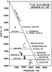 Figure 6.
Pressure-depth profile from Beaver County, Oklahoma that illustrates
obvious underpressured compartments in the upper and lower Morrow
stratigraphic interval. Upper Morrow p-d values are lower than values in
the deeper lower Morrow ‘Keyes’ and Chester compartments, which is a
reversal of the relative pressure values evident in the Keyes area
Figure 6.
Pressure-depth profile from Beaver County, Oklahoma that illustrates
obvious underpressured compartments in the upper and lower Morrow
stratigraphic interval. Upper Morrow p-d values are lower than values in
the deeper lower Morrow ‘Keyes’ and Chester compartments, which is a
reversal of the relative pressure values evident in the Keyes area Figure 7.
Net Keyes sandstone thickness map that delineates paleodrainage patterns
on the underlying eroded Mississippian surface. Net sandstone exceeds
100 ft (30 m) in paleovalleys. A disposal site in the thick Keyes trend
in Sections 9 and 16 has a calculated injectate capacity exceeding 21
million barrels.
Figure 7.
Net Keyes sandstone thickness map that delineates paleodrainage patterns
on the underlying eroded Mississippian surface. Net sandstone exceeds
100 ft (30 m) in paleovalleys. A disposal site in the thick Keyes trend
in Sections 9 and 16 has a calculated injectate capacity exceeding 21
million barrels. Figure 8.
Wireline log characteristics of the Keyes sandstone in T.5N., R.9ECM.,
Cimarron County, Oklahoma. Net sandstone is defined as having positive
filtercake accumulation, spontaneous potential (SP) deflection of > 60
millivolts (mv), density or neutron-density >10% and/or positive
separation (shaded) between microresistivity curves.
Figure 8.
Wireline log characteristics of the Keyes sandstone in T.5N., R.9ECM.,
Cimarron County, Oklahoma. Net sandstone is defined as having positive
filtercake accumulation, spontaneous potential (SP) deflection of > 60
millivolts (mv), density or neutron-density >10% and/or positive
separation (shaded) between microresistivity curves. Figure 9.
Distribution and thickness of net lower Purdy (upper Morrow) sandstone,
NE Rice Field, Texas County, Oklahoma (Harrison, 1990). Areas of sand
accumulation were isolated by mud and silt deposition in the incised
valley. These shale plugs separate fields and reservoirs. Shale valley
walls further confine these sandstones. This results in total encasement
of valley fill sandstone in clay-rich, sealing rock and creation of an
ideal disposal zone. Cross-section A-A’ is shown by
Figure 9.
Distribution and thickness of net lower Purdy (upper Morrow) sandstone,
NE Rice Field, Texas County, Oklahoma (Harrison, 1990). Areas of sand
accumulation were isolated by mud and silt deposition in the incised
valley. These shale plugs separate fields and reservoirs. Shale valley
walls further confine these sandstones. This results in total encasement
of valley fill sandstone in clay-rich, sealing rock and creation of an
ideal disposal zone. Cross-section A-A’ is shown by