![]() Click to view images in PDF format.
Click to view images in PDF format.
GCCrooks
Gap Field, Wyoming: Limitations of  3-D
3-D Seismic Interpretation
By
Robert E. Wellborn1
Search and Discovery Article #40065 (2002)
*Adapted for online presentation from the Geophysical Corner
column in AAPG Explorer November, 2000, entitled “Finding Limits of 3-D
Seismic,” and prepared by the author. Appreciation is expressed to the
author, to R. Randy Ray, Chairman of the AAPG Geophysical Integration Committee,
and to Larry Nation, AAPG Communications Director, for their support of this
online version.
1Chief geologist, Wold Oil Properties, Casper, Wyoming
Some of you
may recall the early 1950s, when the reflection seismograph was making great
advances. Some advisors said conventional petroleum geology exploration was
being replaced and it might be wise to change college majors to some other
field, perhaps geophysics. At the same ![]() time
time![]() , I recall graduate school at
Berkeley, with professor C.M. Gilbert musing that “geology is an art, not a
science,” referring to the importance of an educated guess. The talk about being
replaced was flat-out wrong, but Gilbert's idea still remains true.
, I recall graduate school at
Berkeley, with professor C.M. Gilbert musing that “geology is an art, not a
science,” referring to the importance of an educated guess. The talk about being
replaced was flat-out wrong, but Gilbert's idea still remains true.
Admittedly
the giant strides in the science of seismology, including ![]() 3-D
3-D![]() and 4-D seismic,
coherency cubes, complex processing parameters and the like, are mind boggling
to many of us. It might be easy for some individuals to succumb to the final
seismic product as being “gospel” -- and perhaps being able to replace
old-fashioned geology. However, there are circumstances where the seismic can
begin to fail us, particularly in steep-dip areas where reliable reflection
and 4-D seismic,
coherency cubes, complex processing parameters and the like, are mind boggling
to many of us. It might be easy for some individuals to succumb to the final
seismic product as being “gospel” -- and perhaps being able to replace
old-fashioned geology. However, there are circumstances where the seismic can
begin to fail us, particularly in steep-dip areas where reliable reflection
![]() migration
migration![]() becomes more difficult. And even worse than recording “no-data” in
these steep-dip areas, we sometimes see erroneous events “sneaking in,” which
can lead to an incorrect structural interpretation.
becomes more difficult. And even worse than recording “no-data” in
these steep-dip areas, we sometimes see erroneous events “sneaking in,” which
can lead to an incorrect structural interpretation.
Various
geophysicists have told me they have encountered a similar problem, as
illustrated by the ![]() 3-D
3-D![]() seismic program over Crooks Gap Anticline in Fremont
County, Wyoming.
seismic program over Crooks Gap Anticline in Fremont
County, Wyoming.
|
|
Click here for sequence of Figure 3a and Figure 3b.
Click here for sequence of Figure 4a and Figure 4b.
Click here for sequence of Figure 5a and Figure 5b.
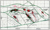
Crooks Gap Field is in the northeast corner of the Great Divide
Basin (Figure
1), in a structurally complex area thought to be suited to As a result of this survey (Figure 2), three different operators with their own geophysical departments drilled three unsuccessful Crooks Gap option wells. All drilled close to prognosis to the Mowry Shale, which then became anomalously thick due to a fault repeated and overturned section caused by multiple bedding plane detachments. Also, all of the beds on the southwest flank rapidly roll over into very steep to vertical dips. Figure 3a is a geologic cross section through some earlier wells across Crooks Gap Field, and defines an anticlinal axial plane dipping at 18 degrees from vertical. Significantly, the #12 well has dipmeter dips changing from the northeast to the southwest within the Frontier Formation.
The first indications of problems with the Of particular interest is the strong southwest continuation of the deep Phosphoria-Tensleep (Pt) seismic events. In two wells, which penetrated the Paleozoic at Crooks Gap, E-log correlations indicate overturned beds in the Phosphoria, contrary to the flat seismic reflections. Although the farmees were aware of the geologic discrepancies, they decided the seismic data were too strong to the southwest to be ignored. They programmed the #25 well to penetrate both the Dakota and Nugget reservoirs in a structural position high to the #6 well (Figure 4b, dashed orange and yellow lines). Formations came in as expected to the top of the Mowry, followed by a "wadded up" Mowry Shale, and the hole ended up on the steep southwest flank of the structure (Figure 4a), missing the crest at the Dakota level. Undaunted by the previous failure, another company took a farmout to drill a Nugget test just 800 feet southeast of the #25 dry hole. With velocity problems seemingly resolved, the #22 location was chosen on what was thought to be an antithetic forelimb detachment thrust (Figure 5b). Both the Dakota and Nugget formations were interpreted to be unusually high (dashed orange and yellow lines). Unfortunately, this attempt was even farther off-structure, and drilled near-vertical Mowry Shale for nearly 1,000 feet (Figure 5a). With a prior structural analysis from existing well data, this failure might have been avoided. The postulated antithetic thrust was large enough that it should have been recognized in nearby wells, particularly the #25 hole; however, evidence of a fault is lacking. On the seismic section, this fault appears to die out too rapidly upward and does not displace or even fold the Frontier seismic events. A third operator drilled yet another dry hole at the north end of the anticline based on similar migrated seismic data, believing they could get higher than the previous wells. Instead, the hole ended up structurally low, in 60-degree southwest dips, much like the other examples. A review of previous hole deviations in this area could have ruled out this third attempt, since wellbore deviation plots indicate these earlier wells were on the structural axis at Dakota level.
Now one might ask, "what happened?" I was advised by one
geophysicist that the problem lies in the complex velocities associated
with the thrust faults and in the At this point a structural geologist should have been involved, using perhaps as much art as science -- and an occasional “educated guess.” Detailed structural studies, utilizing all possible data, such as field mapping, air photos and well control, should be done prior to the seismic survey. Structure cross sections should be constructed to compare to the seismic sections (using the same horizontal scale) to determine where and why they might differ. One should honor the dipmeters as they are usually more accurate in the immediate area than the seismic. Lacking dipmeter data, one can use directional surveys or even non-directional hole deviation surveys, in locating a structure's crest. Most importantly, when an exploration company is gathering seismic in a complex structural area, their geophysicist should also be an experienced structural geologist, or the structural geologist should be a competent geophysicist. Since most of us lack dual expertise, it is essential the geophysicist and structural geologist work together to avoid incorrect interpretation and costly mistakes. |
 Figure
1. Location of Crooks Gap Field in the northeastern corner of the Great
Divide Basin, Wyoming.
Figure
1. Location of Crooks Gap Field in the northeastern corner of the Great
Divide Basin, Wyoming.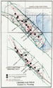 Figure 2. Comparison of a Dakota
 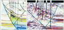 Figure 3. Detailed comparison of structural cross section using
well data (a) to a
Figure 3. Detailed comparison of structural cross section using
well data (a) to a 