Extensional Fault-Bend Folding and Synrift Deposition: An Example from the Central Sumatra Basin, Indonesia*
John H. Shaw1, Stephen C. Hook1, and Edward P. Sitohang2
Search and Discovery Article #40004 (1999)
1Texaco Exploration and Production
Technology Dept., 3901 Briarpark, Houston, Texas 77042.
2PT CALTEX
Pacific Indonesia, Rumbai, Pekanbaru 28271, Indonesia.
* Published in AAPG Bulletin, V. 81, No. 3 (March 1997), P. 367-379; Figures 2,4, and 10 revised for online presentation.
Abstract
We describe an analytical method for interpreting
the geometry and structural history of asymmetric half grabens in
rift basins with extensional fault-bend fold theory. Using
seismic reflection profiles from the Central Sumatra basin and
balanced forward ![]() models
models![]() , we show how local variations in tectonic
subsidence relative to deposition rates yield distinctive
patterns of folded synrift strata and unconformities that record
basin history. If the deposition rate exceeds the local
subsidence rate, folded growth strata form upwardly narrowing
kink bands that have been described previously as growth
triangles. In contrast, if the deposition rate is less than or
equals the local subsidence rate, growth strata are folded and
truncated at the surface on half-graben margins. Subsequent
increases in deposition rate relative to subsidence rate form
angular unconformities near the half-graben margins. These
unconformities develop without the necessity of erosion and are
folded by continuing fault slip. Strata above and below the
unconformities are concordant in the deeper parts of the half
grabens. Thus, angular unconformities on half-graben margins are
helpful for defining sequence boundaries that may reflect changes
in deposition and tectonic subsidence rates. In addition,
fault-bend fold interpretations yield fault geometry and measures
of
, we show how local variations in tectonic
subsidence relative to deposition rates yield distinctive
patterns of folded synrift strata and unconformities that record
basin history. If the deposition rate exceeds the local
subsidence rate, folded growth strata form upwardly narrowing
kink bands that have been described previously as growth
triangles. In contrast, if the deposition rate is less than or
equals the local subsidence rate, growth strata are folded and
truncated at the surface on half-graben margins. Subsequent
increases in deposition rate relative to subsidence rate form
angular unconformities near the half-graben margins. These
unconformities develop without the necessity of erosion and are
folded by continuing fault slip. Strata above and below the
unconformities are concordant in the deeper parts of the half
grabens. Thus, angular unconformities on half-graben margins are
helpful for defining sequence boundaries that may reflect changes
in deposition and tectonic subsidence rates. In addition,
fault-bend fold interpretations yield fault geometry and measures
of ![]() horizontal
horizontal![]() extension, both of which control three-dimensional
half-graben geometry and accommodation space. We show how
along-strike variations in fault geometry produce intrabasinal
structures that may form prospective fairways or local
depocenters.
extension, both of which control three-dimensional
half-graben geometry and accommodation space. We show how
along-strike variations in fault geometry produce intrabasinal
structures that may form prospective fairways or local
depocenters.
Introduction
Half grabens form during crustal extension that
is accommodated by normal faults, which commonly flatten with
depth, causing collapse of the hanging wall and formation of
inclined rollover panels (Hamblin, 1965). Many workers have
presented geometric and physical ![]() models
models![]() of hanging-wall collapse
along vertical or steeply dipping shear surfaces (e.g., Gibbs,
1983; Jackson and Galloway, 1984; White et al., 1986; Rowan and
Kligfield, 1989; Groshong, 1990; Nunns, 1991; White and Yielding,
1991; Withjack et al., 1995), including Coulomb shear along
active fold hinges (Xiao and Suppe, 1992). The theory of Xiao and
Suppe (1992) described how these active fold hinges, called
active axial surfaces, are pinned at depth to fault bends and
extend upward through prerift and synrift sections. As strata
pass through these active axial surfaces due to fault slip, they
are deformed into kink bands or inclined rollover panels. In
areas of continuously curved or listric normal faults, where
fault geometry can be strongly affected by sedimentary
compaction, hanging-wall shear is generally distributed
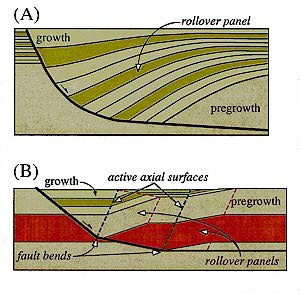
throughout the hanging-wall block (Figure 1A). Typically,
syntectonic hanging-wall strata thicken gradually and fan toward
the fault. In contrast, slip along normal faults composed of two
or more planar segments produces hanging-wall shear along
discrete axial surfaces related to fault bends (Figure 1B). Above
faults composed of planar segments, rollovers are composed of
planar segments, and growth strata thicken abruptly toward the
fault above rollover panels.
of hanging-wall collapse
along vertical or steeply dipping shear surfaces (e.g., Gibbs,
1983; Jackson and Galloway, 1984; White et al., 1986; Rowan and
Kligfield, 1989; Groshong, 1990; Nunns, 1991; White and Yielding,
1991; Withjack et al., 1995), including Coulomb shear along
active fold hinges (Xiao and Suppe, 1992). The theory of Xiao and
Suppe (1992) described how these active fold hinges, called
active axial surfaces, are pinned at depth to fault bends and
extend upward through prerift and synrift sections. As strata
pass through these active axial surfaces due to fault slip, they
are deformed into kink bands or inclined rollover panels. In
areas of continuously curved or listric normal faults, where
fault geometry can be strongly affected by sedimentary
compaction, hanging-wall shear is generally distributed
throughout the hanging-wall block (Figure 1A). Typically,
syntectonic hanging-wall strata thicken gradually and fan toward
the fault. In contrast, slip along normal faults composed of two
or more planar segments produces hanging-wall shear along
discrete axial surfaces related to fault bends (Figure 1B). Above
faults composed of planar segments, rollovers are composed of
planar segments, and growth strata thicken abruptly toward the
fault above rollover panels.
Extensional Fault-Bend Folding
Purely rigid-block translation of the hanging wall over a normal fault that flattens with depth produces a large void between fault blocks that cannot be supported at depth. Collapse of hanging walls into these voids forms inclined fold limbs or "rollovers" above nonplanar faults (Hamblin, 1965); these rollovers have been observed in rift basins worldwide (e.g., Bally, 1983; James, 1984; Nunns, 1991). Xiao and Suppe (1992) modeled this hanging-wall collapse by Coulomb shear along inclined axial surfaces (Figure 2). During progressive fault slip, the hanging wall is sheared through active axial surfaces that are pinned to bends in the fault.
The geometries of normal faults and associated rollover panels control the size and shape of accommodation spaces in half grabens where sediments can be deposited. Hanging-wall subsidence induced by fault slip produces an accommodation space in the half graben, which is defined by the maximum structural relief of the top pregrowth horizon between hanging-wall and footwall blocks (Figure 3A). In situations where sediments evenly fill or overfill this accommodation space above a single normal fault that flattens with depth, synrift strata are thickest above the most inclined fault segments and thin in the direction that the fault shallows (Figure 2). If normal faults are composed of two or more planar segments, separate compartments develop above each fault segment in the half grabens (Figure 3B). Compartments are separated from each other by active axial surfaces that are pinned to fault bends. Each half-graben compartment has a distinct subsidence rate that is controlled by the dip of the underlying fault segment.The rollover accommodation space is defined by the structural relief across a rollover panel, which represents the maximum structural relief between adjacent half-graben compartments (Figure 3B).
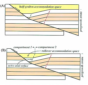 |
Figure
3 Extensional fault-bend fold |
| If sediments are coevally deposited in adjacent compartments (i.e., sediments are deposited on both sides of an active axial surface), sediments overfill the rollover accommodation space (see Figure 4C, compartments 1 and 2). Due to differences in subsidence rate and rollover accommodation space, deposition rates and strata thicknesses typically change between adjacent half-graben compartments. During progressive fault slip, however, strata are translated between compartments as they migrate through active axial surfaces. In addition to this translation, strata are folded around active axial surfaces and incorporated into kink bands or rollover panels that widen with progressive fault slip. Rollover widths of growth strata reflect the amount of fault slip that has occurred since their deposition. Sediments deposited early in the rift history, therefore, record wider rollover widths than do sediments deposited later. As a result, these syntectonic strata form upwardly narrowing rollover panels called growth triangles (Figure 4) (Xiao and Suppe, 1992).Growth triangles are bounded by active axial surfaces and inactive axial surfaces in growth strata, which are called growth axial surfaces. Growth axial surfaces record the positions of sediments initially deposited along active axial surfaces and, therefore, record paleoboundaries between adjacent half-graben compartments. As a result of different subsidence and deposition rates between compartments, strata abruptly change thickness across growth axial surfaces (Figure 4). | |
| Figure 4
Sequential |
Note that the growth axial surface above rollover panel 1 dips more steeply in strata that overfilled the half-graben accommodation space and dips more gently in strata that slightly underfilled the half-graben accommodation space. |
In contrast, where sediments underfill or exactly
fill the rollover accommodation space, other fold geometries
result (see Figure 4C, compartments 2 and 3). Under these
conditions, deposition is confined to the more rapidly subsiding
compartment 2, which is separated from the adjacent compartment 3
by an active axial surface (Figure 4). Growth strata deposited in
the more rapidly subsiding compartment 2, however, are translated
into the adjacent compartment 3 due to ![]() horizontal
horizontal![]() motion of the
hanging wall; this motion is induced by fault slip. As these
growth strata are sheared through the active axial surface, they
are folded into the rollover panel and crop out in angular
fashion at the surface. Although subsequent erosion may further
alter the geometry of growth strata at the surface, the angular
exposure is initially developed by folding and translation of
strata into areas of nondeposition. Subsequent deposition of
either postrift or synrift sediments above the truncated growth
strata generates an angular unconformity. Typically, angular
unconformities are interpreted to reflect distinct periods of
deformation, erosion, and then deposition; however, the growth
fault-bend fold
motion of the
hanging wall; this motion is induced by fault slip. As these
growth strata are sheared through the active axial surface, they
are folded into the rollover panel and crop out in angular
fashion at the surface. Although subsequent erosion may further
alter the geometry of growth strata at the surface, the angular
exposure is initially developed by folding and translation of
strata into areas of nondeposition. Subsequent deposition of
either postrift or synrift sediments above the truncated growth
strata generates an angular unconformity. Typically, angular
unconformities are interpreted to reflect distinct periods of
deformation, erosion, and then deposition; however, the growth
fault-bend fold ![]() models
models![]() in Figure 4 demonstrate that angular
unconformities can develop in half grabens without erosion or a
hiatus in deformation due to increases in deposition rate
relative to subsidence rate, where half-graben compartments
change from sediment-underfilled to overfilled conditions. In
Figure 4D, strata both above and below the angular unconformity
are syntectonic and become concordant in the deeper parts of the
half graben.
in Figure 4 demonstrate that angular
unconformities can develop in half grabens without erosion or a
hiatus in deformation due to increases in deposition rate
relative to subsidence rate, where half-graben compartments
change from sediment-underfilled to overfilled conditions. In
Figure 4D, strata both above and below the angular unconformity
are syntectonic and become concordant in the deeper parts of the
half graben.
Examples from the Central Sumatra Basin
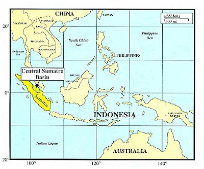 |
Figure 5 Map showing the location of the Central Sumatra basin on the Island of Sumatra, Indonesia. |
In the Central Sumatra basin (Figure 5), growth
triangles and unconformities, similar to those generated in our
fault-bend fold ![]() models
models![]() , are observed in seismic images of
Tertiary lacustrine, fluvial, and marine strata (Figure 6). Using
a trough in Central Sumatra as an example for our model, we
interpret the structural geometry and history of half grabens as
extensional fault-bend folds. Distinct axial surfaces separating
inclined from near-
, are observed in seismic images of
Tertiary lacustrine, fluvial, and marine strata (Figure 6). Using
a trough in Central Sumatra as an example for our model, we
interpret the structural geometry and history of half grabens as
extensional fault-bend folds. Distinct axial surfaces separating
inclined from near-![]() horizontal
horizontal![]() strata in this basin (Figure 6)
suggest that the underlying normal faults are composed of planar
segments. Furthermore, the migrated seismic reflection profiles
in Figure 6 image strata above and below the angular
unconformities that become concordant toward the center of the
troughs. Based on extensional fault-bend fold
strata in this basin (Figure 6)
suggest that the underlying normal faults are composed of planar
segments. Furthermore, the migrated seismic reflection profiles
in Figure 6 image strata above and below the angular
unconformities that become concordant toward the center of the
troughs. Based on extensional fault-bend fold ![]() models
models![]() (Figure 4),
these lateral changes from discordant to concordant strata
suggest significant increases in deposition rates relative to
subsidence rates through time. Collectively, these patterns of
folded strata enable us to decipher the structural and
depositional history of these half grabens using extensional
fault-bend fold theory (Xiao and Suppe, 1992).
(Figure 4),
these lateral changes from discordant to concordant strata
suggest significant increases in deposition rates relative to
subsidence rates through time. Collectively, these patterns of
folded strata enable us to decipher the structural and
depositional history of these half grabens using extensional
fault-bend fold theory (Xiao and Suppe, 1992).
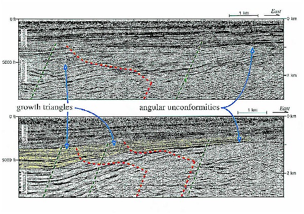
Figure 6 Examples of growth triangles and angular unconformities in half grabens that are imaged in migrated seismic reflection profiles from the Central Sumatra basin. Similar growth triangles and unconformities are modeled in Figure 4 and are used to decipher the underlying fault geometry and structural history of the basin. Note how strata above the angular unconformities in the east become concordant to the west in the deeper parts of the half grabens. Datum (0 km) is sea level.
The migrated seismic reflection profile in Figure 7 , which is displayed in depth,
images a half graben in the Central Sumatra basin where Oligocene
strata thicken westward above an east-dipping normal fault that
is locally defined by a prominent fault-plane reflection. In the
uppermost part of the synrift section, at least three axial
surfaces separate ![]() horizontal
horizontal![]() strata on the left (west) from
inclined strata in rollover panels on the right (east) (Figure 7B). In the extensional fault-bend
fold
strata on the left (west) from
inclined strata in rollover panels on the right (east) (Figure 7B). In the extensional fault-bend
fold ![]() models
models![]() (Figure 4), the steeply dipping axial surfaces that
deform the synrift section are pinned at depth to bends in the
basin-forming normal fault. Therefore, we interpret these fold
hinges in Figure 7 as active axial
surfaces that are each pinned at depth to a discrete bend in the
underlying normal fault. Active axial surfaces are best located
by identifying changes in the dip of reflections in the uppermost
growth sequences (Figures 6, 7). These dip changes should be
consistent with the sense of simple shear induced by the fault
bend. For the concave-upward fault shapes described here, the bed
dip should be antithetic to the fault dip and should steepen in
the direction that the fault deepens. Alternatively,
convex-upward fault bends may yield panels that are synthetic to
the fault dip (Xiao and Suppe, 1992). In Figure
7, we extended the westernmost active axial surface downward
through fold hinges and used this orientation, which likely
reflects the Coulomb shear angle (Xiao and Suppe, 1992), to help
define the other, more poorly imaged axial surfaces. In other
cases, fold hinges may be more curved and less discrete if the
fault bends also are curved. Thus, a range of axial surface dips
(inclined shear orientations) should be tested (e.g., White et
al., 1986; Groshong, 1990). Moreover, subtle dip changes in
rollover panels are generally produced from subtle changes in
fault dip or other processes (e.g., differential compaction), and
the interpreter must decide upon the appropriate resolution of
structural dip changes.
(Figure 4), the steeply dipping axial surfaces that
deform the synrift section are pinned at depth to bends in the
basin-forming normal fault. Therefore, we interpret these fold
hinges in Figure 7 as active axial
surfaces that are each pinned at depth to a discrete bend in the
underlying normal fault. Active axial surfaces are best located
by identifying changes in the dip of reflections in the uppermost
growth sequences (Figures 6, 7). These dip changes should be
consistent with the sense of simple shear induced by the fault
bend. For the concave-upward fault shapes described here, the bed
dip should be antithetic to the fault dip and should steepen in
the direction that the fault deepens. Alternatively,
convex-upward fault bends may yield panels that are synthetic to
the fault dip (Xiao and Suppe, 1992). In Figure
7, we extended the westernmost active axial surface downward
through fold hinges and used this orientation, which likely
reflects the Coulomb shear angle (Xiao and Suppe, 1992), to help
define the other, more poorly imaged axial surfaces. In other
cases, fold hinges may be more curved and less discrete if the
fault bends also are curved. Thus, a range of axial surface dips
(inclined shear orientations) should be tested (e.g., White et
al., 1986; Groshong, 1990). Moreover, subtle dip changes in
rollover panels are generally produced from subtle changes in
fault dip or other processes (e.g., differential compaction), and
the interpreter must decide upon the appropriate resolution of
structural dip changes.
| Only one segment of the fault is defined
by a fault-plane reflection on the seismic profile in Figure 7; the adjacent fault
segments are not imaged. The dips of the folded strata,
the imaged fault segment, and the axial surfaces,
however, can be used to predict the complete fault shape
(Groshong, 1990; Dula, 1991; Xiao and Suppe, 1992). In
extensional fault-bend folds, the magnitude of deflection
of strata in a rollover panel is equal to the magnitude
of fault deflection over the same width measured along
the hanging-wall shear (axial surface) orientation
(Figure 8). In Figure 8, reflections define an axial
surface dip of 66°W and a bed dip of approximately 15°W
in the westernmost rollover panel. Basing our prediction
on the direction and magnitude of deflection of strata in
the kink band, we believe that the fault steepens to a
dip of about 39°E in the region west of the fault-plane
reflection. Similar analyses for the remaining fault
segments yield the entire fault trace on the seismic
profile (Figure 7B). Along YY' in
Figure 7, the fault consists of
several segments that generally flatten with depth to a
near- |
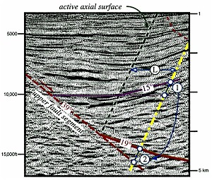 Figure 8 Fault
geometry derived from rollover shape. Enlarged portion of
the seismic line in Figure 7 annotated with a folded
horizon, an active axial surface, and the lower fault
segment (solid red line) based on fault-plane reflections
(see Figure 7A). The dip of the upper fault segment
(dashed red line) is derived from the rollover geometry.
The deflection of the folded horizon (1), measured at a
distance (L) along a line parallel to the |
By identifying active axial surfaces and
determining fault geometry, we have defined two basic geometric
elements of extensional fault-bend folds. Also significant,
however, are the positions of inactive axial surfaces, which
define the widths of rollover panels. In Figure
7, inactive axial surfaces in synrift section (growth axial
surfaces) are readily observed in the uppermost synrift section
because they bound dip domains of growth triangles. In contrast,
the positions of inactive axial surface in pregrowth or basement
sections are not as apparent. A fundamental relation between
kink-band width and fault slip, however, enables us to define the
positions of inactive axial surfaces. In extensional fault-bend
folds above a single normal fault that flattens with depth, the
true widths of all antithetic kink bands or rollover panels are
the same (Figure 9). This kink-band width is a measure of
![]() horizontal
horizontal![]() extension and records the offset of any pregrowth
horizon measured between lines parallel to the hanging-wall shear
(axial surface) orientation that are pinned to correlative
hanging-wall and footwall cutoffs (Figure 9). In the example from
the Central Sumatra basin (Figure 7), we
define the fault offset of the top pregrowth (basement) horizon
based on the fault shape and reflections tied from well control.
Based on the fault-bend fold
extension and records the offset of any pregrowth
horizon measured between lines parallel to the hanging-wall shear
(axial surface) orientation that are pinned to correlative
hanging-wall and footwall cutoffs (Figure 9). In the example from
the Central Sumatra basin (Figure 7), we
define the fault offset of the top pregrowth (basement) horizon
based on the fault shape and reflections tied from well control.
Based on the fault-bend fold ![]() models
models![]() , this fault offset measured
between lines parallel to the hanging-wall shear orientation
equals the width of all antithetic kink bands developed in the
half graben. Therefore, the offset of the top basement horizon
across the normal fault in Figure 7 can
be used to define the positions of inactive axial surfaces in the
rest of the half graben.
, this fault offset measured
between lines parallel to the hanging-wall shear orientation
equals the width of all antithetic kink bands developed in the
half graben. Therefore, the offset of the top basement horizon
across the normal fault in Figure 7 can
be used to define the positions of inactive axial surfaces in the
rest of the half graben.
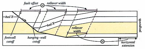
Figure 9 An extensional fault-bend fold model with two rollover panels developed above bends in a normal fault that flattens to a
horizontal
detachment. The widths of both rollover panels are the same and are equal to the
The recognition of axial surface shapes and positions in growth and pregrowth sections, along with the determination of fault geometry, describes the trough imaged in Figure 7 as a half graben developed by extensional fault-bend folding. Proper application of fault-bend folding theories yields area-balanced and retrodeformable interpretations (Suppe, 1983; Xiao and Suppe, 1992). Retrodeformable sections can be kinematically restored to a reasonable, predeformation state without changes in rock area. To demonstrate the internal consistency of the interpretation in Figure 7B, we generate a balanced-forward model of the trough in Figure 10 using the fault geometry, compacted stratigraphic thicknesses, and shear (axial surface) orientation observed in the seismic profile. The retrodeformable model conserves rock area, avoids gaps between fault surfaces by shear along active axial surfaces, and forms rollover panels that have widths related to fault slip. The final stage of the model in Figure 10 depicts all the major structural elements of the trough imaged in Figure 7, including the shape of the graben, the three growth triangles, and the angular unconformity between Pematang and Sihapas strata. The consistency between the geometries of the reflections and interpretation in Figure 7B and the final model in Figure 10 indicates that our interpretation of the trough as an extensional fault-bend fold is internally consistent and viable.
| The first stage of the sequential forward model in Figure 10 depicts the incipient normal fault and active axial surfaces prior to fault slip. Each stage includes deposition of a major stratigraphic unit with fault slip recorded by the width of the folded synrift strata. In the second through fourth stages, Pematang synrift strata are generally confined to the trough and alternatively fill and slightly underfill the half-graben accommodation space. In the final stage of Figure 10, lowermost Sihapas synrift strata are deposited everywhere and overfill the half-graben accommodation space. This change from underfilled to overfilled conditions implies an increase in deposition rate relative to subsidence rate between Pematang and Sihapas sections. | Figure
10 Sequential, kinematic |
This increase generates an angular unconformity on the basin margin even though strata above and below the unconformity become concordant in the deeper part of the trough. In addition, the dips of the growth axial surfaces reflect this ratio of deposition rate relative to subsidence rate. In the Pematang section, which had a relatively low deposition rate relative to subsidence rate, the growth axial surface has a shallow dip (Figure 7). In contrast, the growth axial surface dips more steeply in the lowermost Sihapas section, which had a higher rate of deposition relative to subsidence rate.
The trough imaged in Figure 7
is one of several Tertiary half grabens in the Central Sumatra
basin that share a similar structural history (Eubank and Makki,
1981; Heidrick and Aulia, 1993). Our interpretation and modeling
of the trough imaged in Figure 7 as an
extensional fault-bend fold has important implications for the
structural and depositional histories of the basin. We conclude
that the master normal fault in the trough flattens with depth
and soles to near-![]() horizontal
horizontal![]() detachment. The growth triangles
imaged on the seismic profiles are consistent with deposition of
the lacustrine and fluvial Pematang Group during formation of the
rift. Based on compacted thicknesses and fault slip recorded in
growth triangles, Pematang strata filled or slightly underfilled
the half-graben accommodation space. Thus, the Pematang
deposition rate was generally equal to or slightly less than the
subsidence rate, producing shallowly dipping growth axial
surfaces (Figure 7). Most significantly,
the Brown Shale member of the Pematang formation, which has
sourced the more than 7 billion barrels of oil recovered from the
basin (Oil & Gas Journal, 1993), corresponds to a very
shallowly dipping segment of the growth axial surfaces (Figure 7B). This shallowly dipping growth
axial surface records a low rate of deposition relative to
subsidence rate that may reflect sediment-starved conditions in a
relatively deep lake, which is an environment suitable for the
deposition and preservation of organic materials. The upward
extension of these growth triangles in the lowermost marine
Sihapas Group also suggests that these sediments were locally
deposited during the latest stages of rifting. We demonstrate
that the angular unconformity on the eastern side of the basin
between Sihapas strata and the dipping Pematang section (Figures
5, 6) could have been generated by a dramatic increase in
deposition rate relative to subsidence rate without significant
uplift and erosion between deposition of fluvial-lacustrine and
marine units. This change in deposition rate relative to
subsidence rate may represent either a decrease in slip rate
during the waning stages of the rift or an increase in the
deposition rate of marine vs. older lacustrine and fluvial
sediments.
detachment. The growth triangles
imaged on the seismic profiles are consistent with deposition of
the lacustrine and fluvial Pematang Group during formation of the
rift. Based on compacted thicknesses and fault slip recorded in
growth triangles, Pematang strata filled or slightly underfilled
the half-graben accommodation space. Thus, the Pematang
deposition rate was generally equal to or slightly less than the
subsidence rate, producing shallowly dipping growth axial
surfaces (Figure 7). Most significantly,
the Brown Shale member of the Pematang formation, which has
sourced the more than 7 billion barrels of oil recovered from the
basin (Oil & Gas Journal, 1993), corresponds to a very
shallowly dipping segment of the growth axial surfaces (Figure 7B). This shallowly dipping growth
axial surface records a low rate of deposition relative to
subsidence rate that may reflect sediment-starved conditions in a
relatively deep lake, which is an environment suitable for the
deposition and preservation of organic materials. The upward
extension of these growth triangles in the lowermost marine
Sihapas Group also suggests that these sediments were locally
deposited during the latest stages of rifting. We demonstrate
that the angular unconformity on the eastern side of the basin
between Sihapas strata and the dipping Pematang section (Figures
5, 6) could have been generated by a dramatic increase in
deposition rate relative to subsidence rate without significant
uplift and erosion between deposition of fluvial-lacustrine and
marine units. This change in deposition rate relative to
subsidence rate may represent either a decrease in slip rate
during the waning stages of the rift or an increase in the
deposition rate of marine vs. older lacustrine and fluvial
sediments.
Controls on Three-Dimensional Basin Geometry
Extensional fault-bend fold ![]() models
models![]() demonstrate
that the sizes and shapes of the accommodation spaces in half
grabens are controlled by normal fault geometries, slip, and
axial surface orientations in the hanging-wall block (Xiao and
Suppe, 1992). These controls also affect three-dimensional basin
geometry; therefore, we apply the analytical techniques used to
interpret and model in two-dimensions to explore and map the
three-dimensional geometry of the half graben.
demonstrate
that the sizes and shapes of the accommodation spaces in half
grabens are controlled by normal fault geometries, slip, and
axial surface orientations in the hanging-wall block (Xiao and
Suppe, 1992). These controls also affect three-dimensional basin
geometry; therefore, we apply the analytical techniques used to
interpret and model in two-dimensions to explore and map the
three-dimensional geometry of the half graben.
The hanging-wall shear orientation can be defined
by observing the dip of axial surfaces in seismic profiles. In
many cases, this dip corresponds to the Coulomb shear angle of
the rocks in extension and is roughly constant in basins composed
of the same rock types (Xiao and Suppe, 1992). Given a roughly
constant hanging-wall shear orientation, first-order highs and
lows within the basin are controlled by normal fault geometry and
slip. Thus, where fault geometry is constant along strike,
intrabasinal highs and lows are controlled by fault slip. Regions
of greater fault slip will have greater subsidence than areas of
less slip. Alternatively, where ![]() horizontal
horizontal![]() extension is constant,
lateral changes in fault inclination also form intrabasinal
structures. Folds above shallowly dipping fault segments will
remain high relative to folds along strike that overlie steeper
fault segments. We explore these effects of fault slip and
geometry in the Central Sumatra trough half graben by using
fault-related fold theory to recognize and map
extension is constant,
lateral changes in fault inclination also form intrabasinal
structures. Folds above shallowly dipping fault segments will
remain high relative to folds along strike that overlie steeper
fault segments. We explore these effects of fault slip and
geometry in the Central Sumatra trough half graben by using
fault-related fold theory to recognize and map ![]() horizontal
horizontal![]() extension and to define fault geometry.
extension and to define fault geometry.
In extensional fault-bend folds that form by
simple shear, the offset of the hanging-wall and footwall cutoffs
of any pregrowth horizon is a measure of ![]() horizontal
horizontal![]() extension
above a normal fault that flattens with depth. This measure is
independent of fault dip magnitude (Figure 9). In Figure 11, we
map this
extension
above a normal fault that flattens with depth. This measure is
independent of fault dip magnitude (Figure 9). In Figure 11, we
map this ![]() horizontal
horizontal![]() extension across the trough imaged in Figure 7 using the hanging-wall and footwall
cutoffs on the top of basement. In general, this
extension across the trough imaged in Figure 7 using the hanging-wall and footwall
cutoffs on the top of basement. In general, this ![]() horizontal
horizontal![]() extension is roughly constant at about 3.3 km over the mapped
area. Thus, we speculate that variations in
extension is roughly constant at about 3.3 km over the mapped
area. Thus, we speculate that variations in ![]() horizontal
horizontal![]() extension
along strike do not significantly affect the lateral geometry of
the trough and its accommodation space. Given this roughly
constant
extension
along strike do not significantly affect the lateral geometry of
the trough and its accommodation space. Given this roughly
constant ![]() horizontal
horizontal![]() extension, we expect to see a direct
correlation between fault geometry and the shape of the
half-graben accommodation space.
extension, we expect to see a direct
correlation between fault geometry and the shape of the
half-graben accommodation space.
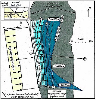 |
Figure
11 Map of the basin-forming normal fault imaged on
seismic profile YY' (Figure 7) and fault offset, measured
between projected hanging-wall and footwall cutoffs of
the top pregrowth horizon (inset). The width of the fault
offset varies only slightly along its mapped extent and
is approximately equal to the magnitude of |
The fault map in Figure 11 was derived from the
fault-plane reflections and rollover geometries in the trough
imaged in Figure 7 and six other
east-west-trending seismic reflection profiles. A simplified
version of this fault geometry with three fault segments is shown
in the three-dimensional model of Figure 12. The fault plane dips
most steeply at shallow depths and flattens through two major
(>10°) bends to a near-![]() horizontal
horizontal![]() detachment. In the center
of the trough along line YY', the intermediate fault panel is
steep and the normal fault flattens to a
detachment. In the center
of the trough along line YY', the intermediate fault panel is
steep and the normal fault flattens to a ![]() horizontal
horizontal![]() detachment at
about -5.3 km (-17,500 ft). Along strike on the northern and
southern edges of the trough, the dips of the intermediate fault
panel are less and the
detachment at
about -5.3 km (-17,500 ft). Along strike on the northern and
southern edges of the trough, the dips of the intermediate fault
panel are less and the ![]() horizontal
horizontal![]() detachment lies at only about
-4.6 km (-15,000 ft) (Figures 11, 12). As a result, the normal
fault has a cuspate or bowl-like shape, with the steepest part of
the intermediate fault segment lying just south of line YY'. A
fault-bend fold model based on this fault shape with laterally
constant
detachment lies at only about
-4.6 km (-15,000 ft) (Figures 11, 12). As a result, the normal
fault has a cuspate or bowl-like shape, with the steepest part of
the intermediate fault segment lying just south of line YY'. A
fault-bend fold model based on this fault shape with laterally
constant ![]() horizontal
horizontal![]() extension (Figure 12) demonstrates that
subsidence and accommodation space are greatest along the center
of the trend.
extension (Figure 12) demonstrates that
subsidence and accommodation space are greatest along the center
of the trend.
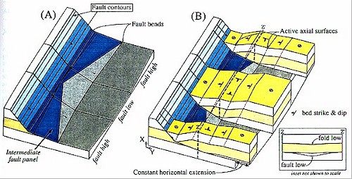
Figure 12 Perspective
views of a three-dimensional fault-bend fold model of the trough
imaged in Figure 7. (A) Cuspate normal fault that flattens with
depth to a near-![]() horizontal
horizontal![]() detachment, which is simplified from
the fault map in Figure 11. (B) Cutaway view of hanging-wall
rollover panels formed by plane strain with all transport vectors
in plane XY.
detachment, which is simplified from
the fault map in Figure 11. (B) Cutaway view of hanging-wall
rollover panels formed by plane strain with all transport vectors
in plane XY. ![]() Horizontal
Horizontal![]() extension, which equals slip on the deep
near-
extension, which equals slip on the deep
near-![]() horizontal
horizontal![]() fault segment, is constant along strike. The
central fault low corresponds to a central basin fold low along
section ZZ' (inset).
fault segment, is constant along strike. The
central fault low corresponds to a central basin fold low along
section ZZ' (inset).
Therefore, we suggest that fault geometry, and not variable displacement, is responsible for defining the structurally lowest depocenter in the trough, which is imaged on strike lines through the basin (Figure 13). In addition to defining low spots, these measures of fault slip and geometry can define structural high points in the troughs that may serve to focus hydrocarbon accumulations. By identifying highs and lows along strike on normal faults, interpreters can quickly recognize depocenters and regional highs (Tearpock and Bischke, 1991), which can be tested by more detailed reflection contouring. Extensional fault-bend fold interpretations provide a method of defining fault planes using fold shape in cases without continuous fault-plane reflections or fault cuts in wells.
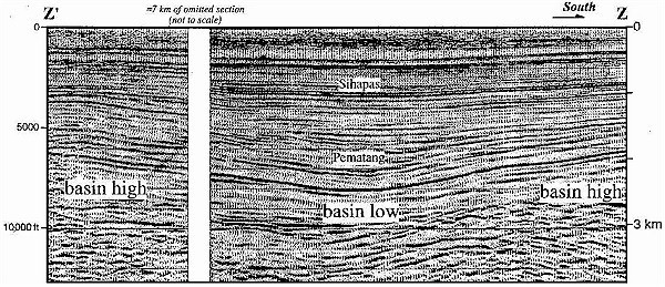
Figure 13 Migrated seismic reflection
profile ZZ' along the strike of the trough shown in Figure 11
that images a central low area bounded to the north and south by
structural highs. Basin highs and lows are caused by lateral
changes in fault geometry, as shown in the model of Figure 12.
The omitted portion of the profile includes an area of younger
folding associated with faults other than the normal fault mapped
in Figure 11. Trace of seismic line ZZ' is shown in Figure 11.
![]() Horizontal
Horizontal![]() scale equals vertical scale; datum (0 km) is sea
level.
scale equals vertical scale; datum (0 km) is sea
level.
Summary and Conclusions
We demonstrated through our interpretation of seismic profiles
and forward ![]() models
models![]() that extensional fault-bend folding has
controlled the structural evolution of a half graben in the
Central Sumatra basin. In addition, we recognized that
syntectonic deposits of fluvial-lacustrine and marine strata form
growth triangles and unconformities, which were produced by
variations between the rates of local deposition and subsidence.
We present a general method for using these patterns of folded
growth strata and fault-bend fold theory (Xiao and Suppe, 1992)
to define basin structure, including fault geometry. Fault and
fold maps based on our interpretations also demonstrated the
effects of variations in fault geometry on half-graben subsidence
and accommodation space. Fault highs and lows along strike in the
trough are overlain by fold highs and lows that form ridges and
depocenters. Collectively, fold and fault shapes provided the
basis for forward kinematic
that extensional fault-bend folding has
controlled the structural evolution of a half graben in the
Central Sumatra basin. In addition, we recognized that
syntectonic deposits of fluvial-lacustrine and marine strata form
growth triangles and unconformities, which were produced by
variations between the rates of local deposition and subsidence.
We present a general method for using these patterns of folded
growth strata and fault-bend fold theory (Xiao and Suppe, 1992)
to define basin structure, including fault geometry. Fault and
fold maps based on our interpretations also demonstrated the
effects of variations in fault geometry on half-graben subsidence
and accommodation space. Fault highs and lows along strike in the
trough are overlain by fold highs and lows that form ridges and
depocenters. Collectively, fold and fault shapes provided the
basis for forward kinematic ![]() models
models![]() of half-graben evolution that
were used to test the viability of our geologic interpretation.
General consistencies between fold and fault shapes generated in
forward
of half-graben evolution that
were used to test the viability of our geologic interpretation.
General consistencies between fold and fault shapes generated in
forward ![]() models
models![]() and imaged on seismic reflection data demonstrate
that extensional fault-bend folding (Xiao and Suppe, 1992) is a
viable theory for the origin of asymmetric half grabens in
basement-involved rift systems. Analytical techniques based on
this theory can be applied with limited seismic reflection data
to generate geometrically and kinematically reasonable
interpretations that define intrabasinal structures prior to
contour mapping of seismic reflections. In addition, fault-bend
fold
and imaged on seismic reflection data demonstrate
that extensional fault-bend folding (Xiao and Suppe, 1992) is a
viable theory for the origin of asymmetric half grabens in
basement-involved rift systems. Analytical techniques based on
this theory can be applied with limited seismic reflection data
to generate geometrically and kinematically reasonable
interpretations that define intrabasinal structures prior to
contour mapping of seismic reflections. In addition, fault-bend
fold ![]() models
models![]() provide new interpretations of unconformities and
folded patterns of syntectonic section that help to decipher the
structural and depositional histories of rift basins.
provide new interpretations of unconformities and
folded patterns of syntectonic section that help to decipher the
structural and depositional histories of rift basins.
References Cited
Bally, A. W., ed., 1983, Seismic expression of structural styles: AAPG Studies in Geology 15, v. 2, variously paginated.
Dula, W. F., 1991, Geometricmodels of listric normal
faults and rollover folds: AAPG Bulletin, v. 75, p.
1609-1625.
Eubank, R. T., and A. C. Makki, 1981, Structural geology of the Central Sumatra back-arc basin: Proceedings of the Indonesia Petroleum Association 10th Annual Convention, p. 153-194.
Gibbs, A. D., 1983, Balanced cross-section construction from seismic sections in areas of extensional tectonics: Journal of Structural Geology, v. 5, p. 153-160.
Groshong, R., 1990, Unique determination of normal fault shape from hanging-wall bed geometry in detached half grabens: Eclogae Geologicae Helvetiae, v. 83, p. 455-471.
Hamblin, W. K., 1965, Origin of "reverse drag" on the downthrown side of normal faults: Geological Society of America Bulletin, v. 76, p. 1145-1164.
Heidrick, T. L., and K. Aulia, 1993, A structural and tectonic model of the Coastal Plains Block, Central Sumatra basin, Indonesia: Proceedings of the Indonesia Petroleum Association, 22 Annual Convention, p. 285-317.
Jackson, M. P. A., and W. E. Galloway, 1984, Structural and depositional styles of Gulf Coast Tertiary continental margin: application to hydrocarbon exploration: AAPG Continuing Education Course Notes Series 25, 226 p.
James, D. M. D., ed., 1984, The geology and hydrocarbon resources of Negara Brunei Darussalam: Muzium Brunei, 164 p.
McClay, K. R., and A. D. Scott, 1991, Experimentalmodels
of hanging wall deformation in ramp-flat listric
extensional fault systems: Tectonophysics, v. 188, p.
85-96.
Nunns, A. G., 1991, Structural restoration of seismic and geologic sections in extensional regimes: AAPG Bulletin, v. 75,
p. 278-297.
Oil & Gas Journal, 1993, Worldwide production report: Oil & Gas Journal, v. 91, p. 63-65.
Rowan, M. G., and R. Kligfield, 1989, Cross section restoration and balancing as an aid to seismic interpretation in extensional terranes: AAPG Bulletin, v. 73, p. 955-966.
Suppe, J., 1983, Geometry and kinematics of fault-bend folding: American Journal of Science, v. 283, p. 684-721.
Tearpock, D., and R. E. Bischke, 1991, Applied subsurface geological mapping: Englewood Cliffs, New Jersey, Prentice-Hall, 648 p.
White, N. J., and G. Yielding, 1991, Calculating normal fault geometries at depth: theory and examples, in A. M. Roberts, G. Yielding, and B. Freeman, eds., The geometry of normal faults: Geological Society Special Publication 56, p. 251-260.
White, N. J., J. A. Jackson, and D. P. McKenzie, 1986, The relationship between the geometry of normal faults and that of the sedimentarylayers in their hanging
walls: Journal of Structural Geology, v. 8, p. 897-909.
in their hanging
walls: Journal of Structural Geology, v. 8, p. 897-909.
Withjack, M. O., Q. T. Islam, and P. R. La Pointe, 1995, Normal faults and their hanging-wall deformation: an experimental study: AAPG Bulletin, v. 79, p. 1-18.
Xiao, H., and J. Suppe, 1992, Origin of rollover: AAPG Bulletin, v. 76, p. 509-525.- The authors thank Hongbin Xiao and John Suppe for helpful insights into their extensional fault-bend fold theory, which provided the foundation for this work. Exceptional reviews by M. Scott Wilkerson and Walter F. Dula, Jr., improved the manuscript. In addition, discussions with Karsani Aulia, Richard E. Bischke, Peter A. Brennan, Chris D. Connors, Paul W. Genovese, Tom L. Heidrick, and Elizabeth A. Lorenzetti provided insights into our structural interpretations and presentation of the theory. Seismic reflection data were provided by PT CALTEX Pacific Indonesia.