![]() Click to view article in PDF format.
Click to view article in PDF format.
GCTying 2-D ![]() Seismic
Seismic![]() Lines in Overthrust Settings*
Lines in Overthrust Settings*
Rob Vestrum1
Search and Discovery Article #41007 (2012)
Posted August 27, 2012
*Adapted from the Geophysical Corner column, prepared by the author, in AAPG Explorer, August, 2012, and entitled "In Overthrust Settings, Tie, Tie (2-D) Again". Editor of Geophysical Corner is Satinder Chopra ([email protected]). Managing Editor of AAPG Explorer is Vern Stefanic; Larry Nation is Communications Director. AAPG©2012
1 Thrust Belt Imaging, Calgary, Canada ([email protected])
In the rough terrain of overthrust settings, 2-D ![]() seismic
seismic![]()
![]() data
data![]() continues to be a standard tool for subsurface mapping - and not only because of economic reasons. Two-D and
continues to be a standard tool for subsurface mapping - and not only because of economic reasons. Two-D and ![]() 3-D
3-D![]()
![]() seismic
seismic![]() surveys are complementary in land environments, because each
surveys are complementary in land environments, because each ![]() data
data![]() type has its own strength and weakness.
type has its own strength and weakness.
Three-D ![]() seismic
seismic![]()
![]() data
data![]() gives us a three-dimensional image volume of the subsurface, with no out-of-plane energy problems or potential to miss structural details between 2-D profiles. With such limitations in 2-D
gives us a three-dimensional image volume of the subsurface, with no out-of-plane energy problems or potential to miss structural details between 2-D profiles. With such limitations in 2-D ![]() seismic
seismic![]()
![]() data
data![]() , one might argue that a better exploration strategy would be to just shoot
, one might argue that a better exploration strategy would be to just shoot ![]() 3-D
3-D![]() surveys and not bother with 2-D
surveys and not bother with 2-D ![]() seismic
seismic![]()
![]() data
data![]() , which may be getting obsolete. However, in land
, which may be getting obsolete. However, in land ![]() seismic
seismic![]() acquisition with rough terrain and heavy vegetation, access restrictions make the logistics difficult and expensive to acquire
acquisition with rough terrain and heavy vegetation, access restrictions make the logistics difficult and expensive to acquire ![]() 3-D
3-D![]()
![]() seismic
seismic![]()
![]() data
data![]() with high density. Two-D surveys give us overall higher fold and much higher resolution - and the improved resolution in the shallow section helps us tie surface geology to the subsurface reflectors.
with high density. Two-D surveys give us overall higher fold and much higher resolution - and the improved resolution in the shallow section helps us tie surface geology to the subsurface reflectors.
Where 2-D and ![]() 3-D
3-D![]()
![]() data
data![]() overlap, the 2-D lines can complement the
overlap, the 2-D lines can complement the ![]() 3-D
3-D![]() interpretation with a higher-resolution perspective. So, for scientific as well as economic reasons, 2-D
interpretation with a higher-resolution perspective. So, for scientific as well as economic reasons, 2-D ![]() seismic
seismic![]()
![]() data
data![]() will continue to be a mainstay in resource exploration in compressional and transpressional geologic settings. One of the major pitfalls when interpreting 2-D
will continue to be a mainstay in resource exploration in compressional and transpressional geologic settings. One of the major pitfalls when interpreting 2-D ![]() seismic
seismic![]()
![]() data
data![]() is dealing with out-of-plane reflections, especially when trying to tie intersecting lines in structured areas. Structural geologists and interpretation geophysicists can understand the problem of reflection event correlation across intersecting depth profiles and overcome the difficulty by considering the direction of propagation of
is dealing with out-of-plane reflections, especially when trying to tie intersecting lines in structured areas. Structural geologists and interpretation geophysicists can understand the problem of reflection event correlation across intersecting depth profiles and overcome the difficulty by considering the direction of propagation of ![]() seismic
seismic![]() energy.
energy.
|
|
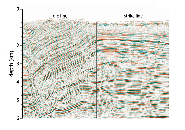
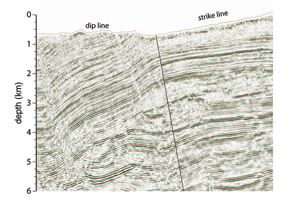
Tying 2-D Profiles in Structure When Figure 1 shows two intersecting depth-migrated lines over a thrusted structure in the foothills of the Andes. The left half of the figure shows the dip line. The dips in the overthrust range between 10 degrees and 30 degrees. The right side if the figure is the intersecting strike line. Note that there is a reasonably good tie between the two lines below 3.5 kilometers depth, where there are relatively flat layers in the footwall. Above the fault (~3.3 kilometers depth at the intersection), the reflectors on the strike line do not line up with the reflectors on the dip line. The layers in the shallow section are dipping, so the reflectors on the strike line are imaged from out of the 2-D plane. Since we illuminate the reflectors at angles near the bedding-plane normal, if one wanted to correlate these dipping reflectors, then one would need to align the sections along the bedding-normal direction. Figure 2 shows the improvement in reflector alignment in the shallow section if we rotate the strike line 10 degrees counterclockwise about the intersecting point at the surface. In this orientation, the correlation is along a direction normal to bedding on the dip line. After the rotation (Figure 2), the reflector alignment is significantly improved between dip and strike lines in the hanging wall. The footwall reflectors, which are more flat, do not tie as well in Figure 2 as with the vertical tie in Figure 1, because the normal-to- bedding direction of these layers is near vertical. Even though the strike line imaged the subsurface reflector outside of its 2-D plane, we still can correlate the two lines by orienting the strike line in the direction normal to bedding. There will still be challenges in creating a When tying 2-D lines in structure, one must not only consider possible differences in static shifts and the phase of the We thank Arcis |
 General statement