![]() Click to view article in PDF format.
Click to view article in PDF format.
Improved Techniques for Acquiring Pressure and Fluid Data in a Challenging Offshore Carbonate Environment*
K.D. Contreiras1, F. Van-Dúnem1, P. Weinheber2, A. Gisolf2, and M. Rueda2
Search and Discovery Article #40433 (2009)
Posted August 10, 2009
*Adapted from expanded abstract prepared for AAPG International Conference and Exhibition, Cape Town, South Africa, October 26-29, 2008.
1Schlumberger ([email protected] )
2Total
3ENI
The combination of low permeability, oil base mud and near
saturated oils presents one of the most challenging environments for fluid
sampling with ![]() formation
formation![]()
![]() testers
testers![]() . Low permeability indicates that the drawdown
while sampling will be high but this is contra-indicated for oils that are
close to saturation pressure. A logical response is to therefore reduce the
flow rate but in wells drilled with OBM an unacceptably long clean-up time
would result.
. Low permeability indicates that the drawdown
while sampling will be high but this is contra-indicated for oils that are
close to saturation pressure. A logical response is to therefore reduce the
flow rate but in wells drilled with OBM an unacceptably long clean-up time
would result.
The Pinda ![]() formation
formation![]() in Block 2 offshore Angola presents just such
a challenge.
in Block 2 offshore Angola presents just such
a challenge. ![]() Formation
Formation![]() mobilities are in the low double or single-digits,
saturation pressure is usually within a few hundred psi of
mobilities are in the low double or single-digits,
saturation pressure is usually within a few hundred psi of ![]() formation
formation![]() pressure
and borehole stability indicates that the wells must be drilled with oil base
mud.
pressure
and borehole stability indicates that the wells must be drilled with oil base
mud.
In the course of several penetrations of the Pinda ![]() formation
formation![]() a
number of attempts were made to acquire representative
a
number of attempts were made to acquire representative ![]() formation
formation![]() samples but
were stymied due to either excessive drawdowns that corrupted the fluid or by
excessive contamination levels that rendered the samples unsuitable for
laboratory analysis. Clearly a more flexible solution was required.
samples but
were stymied due to either excessive drawdowns that corrupted the fluid or by
excessive contamination levels that rendered the samples unsuitable for
laboratory analysis. Clearly a more flexible solution was required.
In this paper we review the results from previous attempts in the
Pinda. We show the pre-job modeling that was done to predict the required flow
rates and the anticipated drawdowns. Ultimately a two-step solution was used.
We first ran a high efficiency pretest-only WFT in order to quickly gather
![]() formation
formation![]() pressure data and mobility data. This data was then used to design
the sampling string which was a combination of an inflatable dual packer with
focused probe. We discuss the decision process that governed the choice of
pump, displacement unit, probe and packer. We pay particular attention to the
unique pump configurations that were required to effectively manage the
drawdowns when using the probe and also to allow sufficient flow rate when
using the dual packer.
pressure data and mobility data. This data was then used to design
the sampling string which was a combination of an inflatable dual packer with
focused probe. We discuss the decision process that governed the choice of
pump, displacement unit, probe and packer. We pay particular attention to the
unique pump configurations that were required to effectively manage the
drawdowns when using the probe and also to allow sufficient flow rate when
using the dual packer.
uExample 1 – Focused Probe Sampling uExample 2 – Dual Packer Sampling
uExample 1 – Focused Probe Sampling uExample 2 – Dual Packer Sampling
uExample 1 – Focused Probe Sampling uExample 2 – Dual Packer Sampling
uExample 1 – Focused Probe Sampling uExample 2 – Dual Packer Sampling
uExample 1 – Focused Probe Sampling uExample 2 – Dual Packer Sampling
uExample 1 – Focused Probe Sampling uExample 2 – Dual Packer Sampling
uExample 1 – Focused Probe Sampling uExample 2 – Dual Packer Sampling
uExample 1 – Focused Probe Sampling uExample 2 – Dual Packer Sampling
|
The Pinda was deposited in a shallow marine environment and is
rich in carbonates and is frequently highly dolomitized. In such complex
reservoirs the acquisition of quality
The interplay between
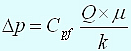
As can be seen the drawdown at the sand face is a function of the mobility (k/μ), the flow rate and the probe size. Therefore in order to minimize the drawdown and stay above the bubble point it is required to either reduce the flow rate or increase the probe size. However neither of these options is without consequence. When the flow rate is reduced we will reduce the drawdown but the resulting very low flow rates imply it will take much longer to clean up the oil base mud filtrate. Similarly, a larger probe size permits a larger flow rate for a given drawdown but also allows for less sealing area for the packer as the flowing area is increased. The sealing success rate must be balanced against the requirements for drawdown and flow rate.
The question is then posed: how to design a sampling program
that accounts for the bubble point and contamination conditions? Looking at Equation
1
we see that four variables affect the drawdown. The
The inflatable dual packer uses two inflatable rubber elements
to isolate and communicate with the reservoir. The spacing between the
packer elements is adjustable however the nominal spacing is about 1.0
metre. Whereas the probes discussed earlier have a flow area that ranges
anywhere from 0.15 to about 2 square inches, the dual packer, when inflated
in an 8.5 inch borehole will isolate a flow area of about 960 square inches.
This obviously leads to a huge reduction in drawdown for a given flowrate and
mobility. We can model the performance of the probes and packers. The
results of this modeling are presented in Table 2
and assume a
As can be seen the inflatable dual packer presents considerable
advantage in terms of reduced drawdown, increased flow rate or both.
However, the advantages of the dual packer do not come without
consideration. The dual packer is typically longer on station. Inflate and
deflate times are longer than the set and retract sequences for a single
probe. Additionally, when considering clean-up time, it is now necessary to
clean up a cylinder that is 1.0 metre in height as opposed to the cone of fluid
associated with a probe type of tool. This can take quite a bit longer.
Finally, extended on-station times and larger tool diameter often dictate the
inflatable dual packer is run drill pipe conveyed instead of on
As the above discussion shows, in lower permeability reservoirs where there is a drawdown constraint due to saturation pressure, we will either be forced to use a dual packer with its attendant considerations or, if we elect to use a probe, forced to pump at very low flow rates. The low flow rates, however, present a problem for sampling oil in a well drilled with oil base mud: clean-up time will be very long. We can mitigate this by using a focused probe sampling tool (Weinheber and Vasques, 2006; Dong et al, 2005; Akurt et al, 2006). Focused sampling has been available for several years now and we describe the basics of operation here.
Consider in Figure 1
a conventional
(non-focused) probe. We show in this figure a packer set against the borehole
wall (left hand side). We assume that the near wellbore fluid, in
yellow-green, is invaded filtrate and that the far field virgin fluid, in
blue, is the desired
Now consider the schematic of the focused sampling probe shown in Figure 2. Note that there have been two significant changes to the focused probe versus the conventional probe. Firstly, the probe has been separated into two distinct flow areas. There is a perimeter ring around the outside which we shall call the guard ring or guard side. In the center there is a flow area which we shall call the sample probe or the sample side. Secondly, there are now two separate flowlines into the tool body. The tool is equipped with a bypass valve that connects or isolates the guard side from the sample side. When this valve is open or connecting we refer to the flow as “commingled”. When the valve is closed or isolating we refer to the flow as “split”. Additionally, the tool carries two pressure gauges: a quartz gauge on the sample side and a strain gauge on the guard side. When the bypass is open we expect these gauges to be reading the same. When the bypass is closed the difference between strain and quartz is the pressure drop across the inner packer. Now consider the flow regime set up by the focused probe during pumping. Note that the same conical flow regime is assumed. In this case the filtrate contamination is going to be captured by the outer flow ring and “guarded” away. The clean reservoir fluid is going to be isolated by the center sample probe and will be captured exclusive of the filtrate. Experience has shown that the best results are achieved when drawdown on the guard side (the strain gauge) is higher than the drawdown on the sample side (the quartz gauge). This pressure profile assures that filtrate is guarded away from the sample probe.
Example 1 – Focused Probe Sampling
We look first at the focused sampling station in Figure
3. Note at the beginning that hydrostatic pressure is ~x600 psi.
Two 10 cc pretests are executed and
At point ‘B’ at about 2900 s the lower pumpout module is stopped and the upper pumpout is started. The flow rate achieved is a very low 1.1 cc/s and the resultant drawdown is only 80 psi. Note that the inner bypass is still open so guard and sample are still reading the same pressure. This 80 psi translates to a flowing mobility of about 21 mD/cp. At about 7400 s the inner bypass is closed and both pumps are activated. This is the “split flow” mode. Initially the guard side pump is started at 2.3 cc/s and the sample side pump is started at 1 cc/s. Note immediately that the pressure on the sample side starts to fall as drawdown increases. It is interpreted that this is likely due to an increase in sample side viscosity as the lower viscosity filtrate is directed to the guard side and the higher viscosity reservoir oil heads towards the sample side. Eventually the pressure on the sample side falls lower than on the guard side (sample side drawdown is higher). As described earlier this is an undesirable situation. Best results are obtained when the drawdown on the guard exceeds the drawdown on the sample so as to encourage the separation of filtrate from reservoir oil. Therefore at about 9400 s the engineer begins stepped increases in the guard side pump speed in order to increase the guard drawdown. By ~7500 s this is achieved and sampling can commence.
Example 2 – Dual Packer Sampling
Multiple attempts to acquire a water sample in the lower part of
the reservoir with a probe only resulted in high drawdown low mobility
pretests. It was therefore decided to inflate the dual packer. Figure
4
shows the sequence. At point ‘A’ we see the lower pump being
used to inflate the packer. During all of time period ‘A’ we are in pump-in
mode to inflate the packers. At point ‘B’ we switch to pump-out mode and
begin the drawdown from the
Sampling near saturated oils from low permeability reservoirs in
a well drilled with oil base mud can provide a significant challenge for a
Of course it is acknowledged that there is a lower limit to permeabilities that may be sampled with the probe type tools. To that end an inflatable dual packer is also included in the tool string and successfully deployed to acquire a water sample and confirm the location of the transition zone. For further information see Contreiras et al, 2008.
Akurt R., et al; 2006, Focusing on Downhole Fluid Sampling and Analysis, Schlumberger Oilfield Review: Winter 2006, p. 4-19.
Beaiji, T, M. Zeybek, R. Crowell, R. Akkurt, S. Al-Dossari, A. Amin,
and S. Crary; 2007, Advanced
Dong, C., C. Del Campo, R. Vasques, P. Hegeman, and N. Matsumoto,
2005,
Hammond, P.S., 1991, One- and Two-Phase Flow During Fluid
Sampling by a
Contreiras, K.K., F. Van-Dúnem, P. Weinheber, A. Gisolf, and M. Rueda; 2008, Improved Techniques for Acquiring Pressure and Fluid Data in a Challenging Offshore Carbonate Environment: SPE 115504, SPE ATCE in Denver, CO., 21-24 September, 2008.
Moran, J.H., and E.E. Finklea, 1962, Theoretical Analysis of
Pressure Phenomena Associated with the
O'Keefe, M., K.O. Eriksen, S. Williams, D. Stensland, and R. Vasques; 2006, Focused Sampling of Reservoir Fluids Achieves Undetectable Levels of Contamination: SPE paper 101084, SPE APOGC, Adelaide, Australia, 11–13 September 2006.
Schlumberger Educational Services Fundamentals of
Weinheber, P.J. and R. Vasques, 2006, New
Weinheber, P.J., A. Gisolf, R.J. Jackson, and I. De Santo, 2008,
Optimizing Hardware Options for Maximum Flexibility and Improved Success in
|