 Click to view posters in PDF format.
PSLeakage Risks Associated with Coal Sequestration in Some Areas of the Central Appalachians: Subsurface, Seismic and Geomechanical Evaluations*
By
Tom Wilson1, Hema Siriwardane1, Xiaochao Tang1, Brian Connolly1, and Jamie Tallman1
Search and Discovery Article #80007 (2007)
Posted July 25, 2007
*Adapted from poster presentation, AAPG Annual Convention, April 1-4, 2007
1West Virginia University, Morgantown, WV 26506-6300 ([email protected])
Potential risks associated with carbon dioxide
sequestration in coal seams are examined in an unmined area of central West
Virginia between the Northern and Central Appalachian coal regions. The study
incorporates subsurface mapping, 2D seismic interpretation and geomechanical
simulation. Isopach maps of interpreted low-density coals reveal significant
thickness variation and discontinuity throughout the 12 square kilometer study
area. Systematic thinning and thickening observed in isopach maps of 200 to 300
foot coal-bearing intervals suggest that deeper faults were periodically active
during deposition. Interval transit time variations observed in 2D seismic lines
across the area also reveal syndepositional reactivation of deeper faults.
Reactivation during and following deposition is likely to have opened and
extended fracture systems through coal-bearing intervals into overlying strata.
Isopach maps of individual low-density intervals reveal pod-like distribution.
Low hydrostatic pressures limit injection to gaseous phase CO2. A
geomechanical ![]() model
model![]() was developed for the site using sonic (DT shear and
compressional) and density logs from a key well in the area.
was developed for the site using sonic (DT shear and
compressional) and density logs from a key well in the area.
Geomechanical simulations predict surface displacements and pore pressures in response to CO2 injection. The likelihood that overburden fracture systems are enhanced through late stage deformation and the presence of considerable heterogeneity and discontinuity in coal distribution, combined with overburden deformations produced by CO2 injection, all represent increased risk of leakage for any coalbed sequestration activities that might be conducted in this or similar areas of the basin.
|
|
The DOE NETL metric for storage permanence is
99% retention after 100 years (see Carbon Sequestration Technology
Roadmap and Program Plan, 2006). This requires detection limits of less
than 0.01%/year. Monitoring, measurement, and
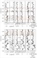
The broader band weight drop data (Figure 1-3) provide improvements in the ability to locate faults, fracture zones, and coal reflections compared to the narrower band vibroseis data (Figure 1-4). 3D seismic coverage using high a frequency vibrator source will provide greater bandwidth and resolution.
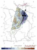
The basement faults underlying the area (Figure 1-2) dip to the northwest. Two-way traveltimes define the areal extent and geometry of the easternmost fault through the area (Figure 1-5). Shallow faults mapped through small offsets or zones of reduced coherence in the reflection seismic response (Figure 1-6) occur along an extension of the deeper margin fault into the near surface. The locations of these minor faults are noted by purple lines on the various maps in this presentation. The influence on the shallower strata produced by syndepositional movements along the deeper faults is transferred up to the southeast. Weight-drop data from the area (Figure 1-6) provide a higher resolution view of near-surface Pennsylvanian and Upper Mississippian strata. However, the signal-to-noise ratio is low and the interpretation is complicated by variable reflection coherence. The interpretations in Figures 1-5, 1-6, and 1-7 reveal shallow folding and faulting.
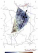
Traveltime differences between reflections observed in the coal-bearing section suggest that the margin fault rotated down to the southwest and west during deposition (see traveltime difference plots—Figures 1-9 and 1-10). Movement appears to have been localized along branching faults that produce local thickening of the coal section to the southwest and west. However, the trend of this 2D line is roughly along strike on the eastern half of the line and cross-strike along its western half so that the relationship of fault movement relative to the trough is complex to interpret. Subsurface coverage provided by the seismic extends a little farther to the southeast than that provided by the well control. Seismic two-way time maps (Figures 2-1 and 2-2) suggest that the region to the southeast (the footwall of the east margin fault) may have been moving downward slightly, relative to the hanging wall block during deposition of the coal-bearing strata. This is suggested by the increased traveltimes observed along the 4 weight-drop lines that extend to the southeast into that area. Limited well and seismic control do not provide a clear check on this interpretation. The traveltime differences through the coal-bearing section (Figures 2-1 and 2-2) do reveal a zone of greater traveltimes that extends north-northwest of the zone of interpreted shallow faults. This zone thins to the northwest as suggested by the traveltime difference plots shown in Figures 1-9 and 1-10. A discontinuous but generally thicker section is also observed in the well-log-derived isopach map of the coal-bearing section.
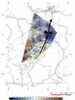
Structure of the Shallow Coal-Bearing Strata Late stage uplift along the outer fault (green fault shown on the seismic line—Figure 1-2) produces a structural high in shallower strata to the northwest. Late stage uplift of the basement block to the northwest produces a syncline over the footwall to the east-southeast along the upward projection of the deeper basement fault (Figures 1-5, 1-6, and 1-7). The Big Injun sandstone lies about 2000 feet beneath the area. Oil production from the Big Injun is concentrated along the west flank of the syncline. Structure on the deepest and shallowest low-density intervals mapped in the area (Figures 2-3 and 2-4) is marked by similar structural lows to the northeast with less pronounced structural rise to the west. The isopach map between these two zones reveals a belt of generally thicker strata trending north-south through the map area (Figure 2-5).
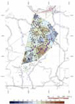
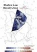
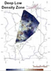
Isopach maps of low-density zones (Figures 2-6 and 2-7) reveal considerable variability over distances of 500 meters or so. The shallow isopach (Figure 2-6) is characterized by pods approximately 0.5 to 1 km in diameter with maximum thickness of between 4 and 9 feet in places that drops to 0 feet in the surrounding (dark blue) areas. The deeper interval (Figure 2-7) is characterized by a zone of thicker section to the west. To the west, the section reaches thicknesses of from 4 to 7 feet. Thickness variations suggest considerable variability in the local depositional environment. Much of this may also be due to erosion during deposition of overlying strata. Considerable thickness variation over small distances makes it unlikely that these potential coal zones could be easily mined. Most of the potential coals mapped in this area reveal considerable heterogeneity in distribution and can probably be classified as unminable in economic terms.
Deformation of overburden strata in response
to CO2 injection was computed using finite element
simulations. The
A geomechanical simulation was conducted
using a
The influence of syndepositional fault displacements on coal deposition is subtle and debatable. Faults with clear offsets at depth rise into the shallow section where fault expression is limited to minor offsets in reflection events accompanied by zones of diminished reflection amplitude. Well-log-derived isopach maps of low-density - possible coal – intervals reveal considerable variation in thickness. The evidence for influence of syndepositional fault displacements during deposition of the coal-bearing strata is unclear, however, the seismic evidence for faulting of the deeper strata leaves little doubt that some faults extend into the strata underlying and possibly extending into the coal-bearing section. In addition, the structural relief on top of the coal-bearing section (60 to 70 feet or so) reveals that the area continued to deform following deposition. Reactivation following deposition is likely to have opened and extended fracture systems through coal-bearing intervals and into overlying strata. The likelihood that overburden fracture systems are enhanced through late-stage deformation and the presence of considerable heterogeneity and discontinuity in coal distribution, combined with overburden deformations produced by CO2 injection may translate into increased risk of leakage for any coalbed sequestration activities that might be conducted in this or similar areas of the basin.
This study was funded through Montana State University Zero Emissions Research Technology (ZERT) research subcontract G137-05-W0221 to West Virginia University ZERT titled Sequestration of Carbon Dioxide in Appalachian Coal Deposits. Our thanks to Dick Bajura (National Research Center for Coal and Energy) for his support of these endeavors. Landmark Graphics Discovery Suite software was used to construct maps and cross sections for the study and Seismic Micro-Technology Inc. Kingdom Suite software was used for the seismic interpretations.
Carbon Sequestration Technology Roadmap and Program Plan, 2006, Office of Fossil Energy, National Energy Technology Laboratory: http://www.fossil.energy.gov/programs/sequestration/publications/programplans/2006/2006_sequestration_roadmap.pdf.
Wells, A., Hammack, R., Veloski,
G., Diehl, R., Strazisar, B., Rauch, H., Wilson, T., and White, C.,
2006, Monitoring, mitigation and Wilson, T. H., 2000, Seismic evaluation of differential subsidence, compaction and loading in an interior basin: AAPG Bulletin, v. 84, no. 3, p. 376-398. Wilson, T., and Miller, R., 2006, Introduction to the special section: Carbon Sequestration/EOR: The Leading Edge, p. 1262-1263. |


