![]() Click
to article in PDF format.
Click
to article in PDF format.
Meander Belt Entrapment of Hydrocarbons, Campbell-Namao Field, Alberta
By
Ralph W. Edie1 and John M. Andrichuk1
Search and Discovery Article #20029 (2005)
Posted July 27, 2005
1Independent geologists, 504 Fording Place, 205 – 9 Avenue S.E., Calgary, Alberta, Canada T2G 0R3 (telephone: 403-269-6084)
Abstract
At Campbell-Namao Field, near Edmonton, Alberta, Lower Cretaceous uppermost Ellerslie Member hydrocarbon-bearing quartz sandstone reservoirs include sandstone bodies with markedly different shapes and origins as follows:
(1) approximately 20 metre-thick sandstone bodies, with an areal extent as great as 518 hectares (2 square miles), that exhibit “fining-upward” response on electric logs and are interpreted as point bar sandstones along a river meander belt.
(2) thin sheet sandstones (5 metres thick) of relatively uniform thickness and widespread areal extent, interpreted as being of marine origin.
Within the interpreted meander belt, there are numerous point bar sandstone bodies, some (but not all) of which contain stratigraphically entrapped hydrocarbons. A roof-seal is provided by a widespread shaly bed. Updip, lateral and downdip sealing is provided by shale-filled channels or oxbows that locally completely surround the point bar sandstone bodies.
Within the interpreted meander belt, 14 shale-filled channels were intersected in boreholes. In the central portions of the shale-filled channels, the compacted shale filling, as measured on electric logs, varies from 14.6 to 23.5 metres (48 to 77 feet). Gas and oil were entrapped in compartmentalized reservoirs and each compartment (point bar or point bar remnant) is characterized by a measurably different subsea gas-oil or oil-water contact. Maximum gross pay thickness is 27.4 metres (90 feet).
In several parts of the meander belt, interpreted point bar sandstones are mainly water-bearing: only point bar sandstones or remnants of point bar sandstones that are completely surrounded by shale-filled channels appear to trap commercial quantities of hydrocarbons. Hydrocarbon entrapment within the thin sheet sandstones is caused by:
(a) updip and lateral facies change from permeable sandstones to shaly beds;
(b) updip and lateral truncation of the thin sheet sandstones by shale-filled deeply entrenched meandering river channels along the concave downdip edge of the meander belt.
Within the field area, the hydrocarbon-bearing portion of the thin sheet sandstones cover an area of 2331 hectares (9 square miles). However, the water-bearing segments of these sandstones extend over a much greater area, beyond the field limits. Total production at Campbell-Namao Field, from both point bar and thin sheet sandstone reservoirs, to the end of March 2002, is 3183 x 106m3 (113 Bcf) and 922 x 103m3 (5.8 million barrels) of 33°A.P.I oil.
In central Alberta, upper Ellerslie meander belts are mapped from electric logs with relatively sparse well control. In exploratory drilling, along those meander belts, hydrocarbon reserves similar in size to those in productive point bar sandstones at Campbell-Namao Field (i.e. 5.8 Bcf gas and 258,000 bbls oil per square mile) can be expected. Moreover, if “bright spot” seismic technology to map upper Ellerslie Member gas accumulations (with or without associated oil columns) can be improved, it should be possible to attain almost 100% success in exploratory drilling along known upper Ellerslie meander belts.
The exploration procedure outlined herein applies to meander belts of various ages world-wide, provided that: (1) the point bar sandstones retain their porosity and permeability; (2) source rocks at sufficient depth and temperature are available to generate hydrocarbons; and (3) the point bar sandstones have a roof-seal.
|
uInternal meander belt entrapment uExternal meander belt entrapment
uInternal meander belt entrapment uExternal meander belt entrapment
uInternal meander belt entrapment uExternal meander belt entrapment
uInternal meander belt entrapment uExternal meander belt entrapment
uInternal meander belt entrapment uExternal meander belt entrapment
uInternal meander belt entrapment uExternal meander belt entrapment
uInternal meander belt entrapment uExternal meander belt entrapment
uInternal meander belt entrapment uExternal meander belt entrapment
uInternal meander belt entrapment uExternal meander belt entrapment
uInternal meander belt entrapment uExternal meander belt entrapment
uInternal meander belt entrapment uExternal meander belt entrapment
uInternal meander belt entrapment uExternal meander belt entrapment
uInternal meander belt entrapment uExternal meander belt entrapment
uInternal meander belt entrapment uExternal meander belt entrapment
uInternal meander belt entrapment uExternal meander belt entrapment
uInternal meander belt entrapment uExternal meander belt entrapment
uInternal meander belt entrapment uExternal meander belt entrapment
uInternal meander belt entrapment uExternal meander belt entrapment
uInternal meander belt entrapment uExternal meander belt entrapment
uInternal meander belt entrapment uExternal meander belt entrapment
uInternal meander belt entrapment uExternal meander belt entrapment
uInternal meander belt entrapment uExternal meander belt entrapment
uInternal meander belt entrapment uExternal meander belt entrapment
uInternal meander belt entrapment uExternal meander belt entrapment
uInternal meander belt entrapment uExternal meander belt entrapment
uInternal meander belt entrapment uExternal meander belt entrapment
uInternal meander belt entrapment uExternal meander belt entrapment
uInternal meander belt entrapment uExternal meander belt entrapment
uInternal meander belt entrapment uExternal meander belt entrapment
uInternal meander belt entrapment uExternal meander belt entrapment
|
IntroductionAt the Campbell-Namao Field near Edmonton, Alberta, natural gas and petroleum occur in compartmentalized sandstone reservoirs associated with a Lower Cretaceous river meander belt. The updip and downdip limits of a segment of that meander belt are shown in Figure 1a. The producing wells within the Campbell-Namao Field during the early stage of field development are shown in Figure 2. The reservoir sandstones occur in the upper part of the Ellerslie Member of the Mannville Group at a depth of 1130 metres (3700 ft.). Within the meander belt, the hydrocarbon pools have a bottom water drive. Most of the producing gas and oil wells have reached their economic limit of production and are now abandoned. No secondary recovery scheme for producing additional oil has been attempted. Total production to the end of March 2002 is 3183 x 106 m3 (113 Bcf) gas and 922 x 103 m3 (5.8 million barrels) of oil. The discovery well for the Campbell-Namao Field was Redwater Leaseholds Campbell 1-28-54-25 W4M (Figure 2). The well was completed as an Ellerslie Member oil well in 1949, and it yielded 33º A.P.I. oil. During early field development, because of a lack of market for the natural gas, gas associated with produced oil was flared. The Alberta Oil and Gas Conservation Board (now Alberta Energy and Utilities Board) attempted to reduce gas flaring by instituting severe production penalties for high gas-oil ratio wells. The gas and oil wells on production at the Campbell-Namao Field 17 years after the initial discovery are shown in Figure 2. In 1966, upon recommendation of the authors, Oakland Petroleums Ltd., drilled the 12-25-54-25 W4M well which resulted in discovery of a new oil pool. This oil pool had a different subsea oil-water contact from that at the Namao pool to the north (Figure. 2), and with continued drilling, Oakland developed a major extension of the Campbell-Namao gas and oil field covering 2395 hectares (9¼ square miles) (Figure 2). From this extension, Oakland Petroleums Ltd. and successor companies produced 380 x 103m3 (2.39 million barrels) of crude oil and 1518 x 106m3 (53.9 Bcf) of gas (i.e., 258,000 bbls. oil and 5.8 Bcf gas per square mile). During the extension development, at least one of the authors performed the well-site geological work at every well drilled by Oakland Petroleums Ltd. and recommended:
The purpose of this paper is to document meander belt entrapment of hydrocarbons in a gas and oil field with relatively close well spacing (mainly 16 to 32 hectare spacing). Within the meander belt, hydrocarbons are entrapped in fining-upward, 20-metre-thick sandstone bodies, interpreted as of point bar origin. The paper demonstrates why some of the fining-upward sandstone bodies within the meander belt, of similar thickness and log trace (on the SP and gamma ray curves) to hydrocarbon bearing sandstones, are 100% water-bearing. The mapping techniques outlined herein may be of interest to exploration personnel worldwide involved in the search for stratigraphically entrapped hydrocarbons in sandstone-shale sequences.
Field Work by the AuthorsAt the wellsite, collection of drill cuttings was carefully supervised at 5-foot or 2-metre intervals and the freshly caught wet cuttings were immediately examined with a binocular microscope. Ellerslie gas-bearing sandstones were clearly recognized by the presence of scattered droplets of gassy brown oil when fragments of the reservoir sandstone were broken with tweezers. Similarly, oil saturated sandstone, characterized by droplets of gassy brown oil in every pore, was identified. Finally, the first appearance of water-wet sandstone, lacking droplets of gassy brown oil, was indicative of the oil-water contact. Thus, the approximate subsea elevation of the gas-oil and oil-water contact at each well was determined from microscopic examination of the wet drill cuttings prior to logging. A more precise subsea elevation of the gas-oil and oil-water contact at each well generally was determined from examination of the sonic and resistivity logs. At Campbell-Namao Field, induction resistivity logs of gas-bearing Ellerslie Sandstone commonly register 12-30 ohm-metres resistivity and oil-bearing sandstones commonly register 8-12 ohm-metres resistivity. Water-bearing sandstones, unless deeply invaded by fresh water based drilling mud filtrate, exhibit less than one ohm-metre resistivity. The oil-water contact at each well was arbitrarily drawn at 4 ohm-metres resistivity. At most wells, the only porosity log run was the gamma ray-sonic so that a combination of neutron-sonic or neutron-density log was not available to determine “cross-over” presence of gas. In most instances, drillstem tests were undertaken to confirm the microscopic and log interpreted gas-oil and oil-water contacts. It should be pointed out that in clean reservoir sandstone, the gas-oil and oil-water contacts can be precisely determined from examination of the sonic and induction resistivity logs. However, this determination is less certain where the gas-oil or oil-water contact coincides with thin shaly beds within the reservoir sandstone.
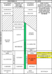
StratigraphyThe term Ostracode zone was first used by Hunt (1950) who described the zone as calcareous fossiliferous black shale, approximately 45 feet thick. Loranger (1951) also described the Ostracode zone and its contained fossils, which include several species of ostracodes, including Metacypris persulcata, pelecypods, and gastropods. From her paleontological studies, Loranger considered the Ostracode zone to be of brackish water origin. Holmden et al. (1997), in isotope studies of Ostracode zone fossils, concluded that the Ostracode zone was mainly a fresh water deposit, perhaps similar to deposits in the present-day Lake Maracaibo, Venezuela. The Blairmore “Calcareous” Member mapped by Glaister (1959) in the foothills of southwestern Alberta is considered by him to be equivalent to the Ostracode zone. Rudkin (1964) states that although the Ostracode zone was originally described (by Loranger) as a faunal zone, it is also a readily mappable lithologic unit. In parts of the Edmonton area, the Ostracode zone, which directly overlies the Ellerslie Member, is considered to be a mainly fresh to brackish water embayment or lake deposit near the edge of the southerly transgressing Boreal sea (McLean and Wall, 1981, Figure 5). In the Campbell-Namao field area, the Ostracode zone consists of two beds (comprising dark brown to black argillaceous limestone or calcareous shale containing shells of gastropods, pelecypods, and ostracodes), characterized by high resistivity on electric logs, separated by a black fissile shale bed (Figure 3). West and southwest of the Campbell-Namao Field, the lower part of the Ostracode zone changes facies to a porous and permeable sheet sandstone which is the reservoir for the Alexander and Big Lake gas fields (Figures 1a and 4). As shown in Figure 1a, the gas-water contact at the Alexander and Big Lake gas fields is –473.7 m and –502.6 m, respectively. The water-bearing parts of the Ostracode zone sandstone bodies, lying downdip to the southwest of the Alexander and Big Lake gas fields, were readily mapped by the authors because the SP, gamma ray, and resistivity logs show clean porous sandstone with very low resistivity. The well control is sufficient to map the extent of the sandstone bodies with a fair degree of precision. It should be pointed out that in the Edmonton area, inconsistencies exist in the geological literature concerning correlation and nomenclature of Ostracode zone members. For example, although Mason (1969b) correctly places the reservoir sandstone at Big Lake Gas Field within the Ostracode zone, at Alexander Gas Field, Mason (1969a) incorrectly places the reservoir sandstone within the Basal Quartz (Ellerslie) member. Similarly, at Alexander Gas Field, Jackson and Bournes (1968) also incorrectly place the Lower Ostracode zone sandstone within the Ellerslie Member. According to Jackson and Bournes (1968), the maximum pay thickness at the Alexander Field is 9.1 metres (30 ft.) and the average pay thickness is 4.6 metres (15 ft.). At the Big Lake Gas Field, Mason (1969b) states that the maximum pay thickness is 5.8 metres (19 ft.) and the average is 3.0 metres (10 ft.). To the end of March 2002, total production from the lower Ostracode zone sandstone at the Alexander and Big Lake gas fields was 4192 x 106 m3 (148.8 Bcf) and 2513 x 106m3 (89.2 Bcf), respectively. Descriptions of the Alexander and Big Lake gas fields, including gas pay isopach maps, were published by Mason (1969a and 1969b). Although Mason (1969a and1969b)described the lower Ostracode Sandstone reservoirs at Alexander and Big Lake gas fields as quartzose sandstones, detailed examination of cores from Midwestern Gas Alexander 10-23-56-1 W5M and Hewitt Big Lake 11-34-53-26 W4M by one of the authors (Edie) shows that these sandstones are composed of approximately 80% quartz grains (with quartz crystal overgrowths) and 20% white to dark gray well rounded chert grains. The sandstone composition is thus similar to Ellerslie equivalent productive Basal Quartz sandstones in the Bantry – Alderson – Taber areas (referred to as “BAT” sandstone) and described by Arnott, et al. (2000) The grain size of the lower Ostracode zone sandstone at Alexander and Big Lake gas fields varies from fine-grained to medium-grained (Wentworth scale) and is distinctly coarser than the underlying upper Ellerslie quartzose sandstones near Edmonton, Alberta. In the cores examined, a few wispy planar to wavy paper-thin dark gray shale partings dip at angles of 5 to 20º. The SP log response of the reservoir sandstone at some of the wells at Alexander and Big Lake fields clearly exhibit a “coarsening – upward” character typical of prograded barrier island marine sandstones (Cant, 1992). However, contradictions to that interpretation are as follows: (1) Except for the presence of scattered granule-size white and dark gray chert pebbles, a few centimeters below the top of the reservoir sandstone, observed in the Midwestern Gas Alexander 10-23-56-1 W5M core, detailed examination of cores from the two wells studied did not indicate any discernible increase in grain size from the bottom to the top of the reservoir sandstone. (2) The SP response of the reservoir sandstone at several wells, including the electric log designated by the letter “L” in Figure 1a and shown in Figure 4, does not show a distinctly “coarsening-upward” feature. According to Williams and Stelck (1975), in late early Albian time, an embayment of the Boreal ocean (Clearwater sea), characterized by the Subarcthoplites ammonite fauna, penetrated southeastward into Alberta and Saskatchewan to the latitude of Calgary. McLean and Wall (1981) show early arms of the Boreal sea as estuaries extending southeastward along the Spirit River and Edmonton channels of Alberta during deposition of Ostracode zone sediments. These boreal seaways were a precursor of the southward widespread marine flooding by the Moosebar-Clearwater sea (Figures 1b and 5). Karvonen(1989) described and mapped an Ostracode zone estuarine facies, (similar to facies within the Gironde estuary on the Atlantic coast of France), in east central Alberta. The evidence for the estuarine facies interpretation include sand-shale tidal bundles and elements of both the Cruziana and Skolithus ichnofacies considered by Karvonen to be indicative of brackish water environments. Following McLean and Wall, (1981), Karvonen interprets that an arm of the Boreal sea extended south and southeastward along the Edmonton channel (and tributary channels) to a point a few kilometers northwest of the Bellshill Lake Oil Field (Figure 5). Based mainly on their widespread lateral extent, their relatively uniform tabular shape and excellent sorting and reservoir quality, the Alexander and Big Lake Gas Field reservoirs are interpreted as marine sheet sandstones. The present authors interpret that at the beginning of Ostracode zone deposition, the shoreline of the Boreal sea within the Edmonton channel was located at the present northwestern limit of the city of Edmonton. At this location, distribution of river mouth, or more likely estuarine mouth, sands by wave induced currents formed barrier islands. Under stable or falling sea level, it is suggested that the barrier islands may have prograded westward to form sheet sandstones as shown in Figure 6. Natural gas was trapped at the updip limit of the reservoir sandstones. The equivalent lower Ostracode zone dark brown to black argillaceous limestone at Campbell-Namao Field is considered to be a widespread lake or brackish water lagoonal bay facies. Karvonen and Pemberton (1997) also interpret progradation of Ostracode zone barrier islands (similar to those shown in Figure 6) in the Jenner-Suffield area, southeastern Alberta. During deposition of middle Ostracode zone strata, it is interpreted that a rise in sea level caused the Boreal sea to advance south and southeastward along the Edmonton and tributary channels to the Bellshill Lake area of Alberta. With the rise in sea level, sands were trapped in the Bellshill Lake estuary mapped by Karvonen (1989) and only clay and organic matter were deposited in the marine Edmonton channel near Edmonton. These clay and organic matter sediments buried the lower Ostracode zone sandstones at Alexander and Big Lake Fields (Figures 1a and 5).
The Ellerslie Member of the Mannville Group (Hunt 1950) consists primarily of well-rounded fine- to very fine-grained (Wentworth scale) quartz sandstones and dark gray shales containing coaly plant fragments. In the Edmonton area, the Ellerslie Member lies on the eroded surface of the Devonian Wabamun Formation. The unconformity is commonly marked by light green waxy-appearing claystone containing siderite spherulites and weathered chert fragments. Locally, thin quartz sandstones are interbedded within the claystone. These lithologies are commonly referred to as the Detrital zone (Deville Member) and are interpreted to represent an ancient soil horizon (Williams, 1963). The eroded surface of the Wabamun Formation (consisting mainly of limestone and very finely crystalline dolomite) exhibits considerable topographic relief. The Ellerslie Member is much thicker in valleys on the erosion surface and is thinner overlying ancient hills. The Ellerslie Member thus ranges in thickness from zero to more than 90 metres (300 feet). On the basis of Ellerslie thickness information obtained from boreholes, Williams (1963) mapped a drainage pattern of trunk rivers and tributaries that had eroded into gently southwesterly-dipping Devonian and Mississippian strata. The drainage pattern indicates that the trunk rivers flowed north to northwest. The Campbell-Namao Field is located near the axis of a main Ellerslie trunk river valley, named by Williams (1963) as the Edmonton channel (Figure 5). In the lower part of the Edmonton channel, the Ellerslie sandstones probably represent braided river deposits similar to present-day braided river deposits along the Niobrara River, Nebraska, including associated levee, crevasse splay and shallow lake deposits described by Ethridge et al. (1999). However in the Edmonton area, during deposition of the uppermost part of the Ellerslie Member, aggradation of sediments had filled the original valley and leveled the surface topography, forming a widespread flood plain. As the rivers continued to flow they excavated channels into pre-existing sediments, meandered, and avulsed across the terrain. As shown in Figure 7, towards the end of Ellerslie deposition, minor hills and valleys on the eroded surface of the Wabamun Formation had little or no discernible influence on the path selected by the river in its journey to the sea. In upper Ellerslie interfluve areas near the city of Edmonton, (Figure 8), the upper part of the Ellerslie Member can be readily correlated on electric logs and consists of two sheet-like quartz sandstones, each about 5 metres thick separated by an electrically resistive marker bed (2 metres thick) (Figure 9). For mapping purposes, these two sandstones are hereby referred to as Peavey and Acheson sandstones. Because of their relatively uniform thickness and widespread lateral extent, the two sandstones are interpreted to have formed by seaward progradation of barrier islands similar to formation of the lower Ostracode zone sandstone at Alexander and Big Lake gas fields. Like many shoreface marine sandstones, both the Peavey and Acheson sandstones contain stratigraphically trapped gas and oil accumulations (Figures 1a, 9, and 10). At Saddle Lake, Alberta, (120 km northeast of Edmonton), an interpreted rapid and substantial rise in sea level at the beginning of Joli Fou time, resulted in preservation of levee and crevasse splay deposits associated with an uppermost Mannville (Colony) meander belt (Edie and Andrichuk, 2003). However, in the Edmonton area, at the beginning of Peavey Sandstone deposition, a marine transgression (forming a ravinement surface as defined by Nummedal et al., 1987) is interpreted to have destroyed levee and crevasse splay deposits leaving an electrically resistive lag (marker bed) in interfluve areas. A wireline core from this marker bed at Pacific British Dominion Woodbend 4-36-51-26 W4M in the interval 4176-79 ft. consists of calcite cemented very fine-grained quartz sandstone containing scattered gastropod shells and shell fragments. A 15-cm-thick dark gray shale bed is present at both the top and bottom of the calcite cemented sandstone. Hayes (1989) has documented marine barrier island retreat caused by marine transgression along a section of the South Carolina Atlantic Coast. This local marine transgression has resulted from a reduction in sediment supply due to construction of dams on the Santee River. Hayes recognized that the marine transgression, which recently cut a submarine terrace across the upper portion of a barrier island, is now eroding into back-barrier island marsh sediments containing tidal creeks and oyster reefs. Thus, Hayes has direct evidence that this local marine transgression will result in a shelly transgressive lag deposit similar to that in the aforementioned 4-36-51-26W4 borehole formed at the toe of the retreating shoreface. According to Hayes, continued transgression may result in the loss of the top 3 to 4 metres of the stratigraphic record.
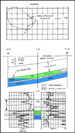
Figures 11-20Meander Belt FaciesAt Campbell-Namao Field, detailed microscopic examination of well bore cuttings by the authors showed that point bar sandstones are composed mainly of fine- to very fine-grained quartz sandstone grading upward to siltstone and silty shale in their upper part. Locally, the lower part of point bars is characterized by medium- to fine-grained quartz sandstone. Average porosity of the reservoir point bar sandstones is 22% as measured on sonic logs. Drillstem tests commonly yielded several thousand feet of light gravity oil or 2 to 8 MMcf gas per day. Rarely, oil flowed to surface on drillstem test. Cores from four wells (Lsd 4 Sec. 6 – T55 R24W4, and Lsd 1 Sec. 1, Lsd 2 Sec. 1 and Lsd 3 Sec. 1 in T55 R25W4) taken from the middle to lower parts of point bars at Campbell-Namao Field exhibit oil stained fine-grained to very fine-grained (Wentworth scale) quartz sandstone. Scattered paper-thin planar to wavy black shale partings dip from near horizontal to 10º. These shale partings are interpreted as clay and organic matter drapes on lateral accretion surfaces defined as inclined stratification (IS) by Thomas et al. (1987). The mud drapes suggest tidal deposits. An example of convolute bedding is shown in Figure 11. In none of the four well cores was there any evidence of basal lag deposits such as coarser sand or intraformational shale-chip conglomerate with a sandy matrix. Although the upper part of point bar sandstones was not cored, there is no evidence within the roughly 20-metre-thick sandstone bodies of multiple fining upward cycles, either in the available cores and samples or on electric logs, implying a single cut and fill. An electric log trace of a resistive gas- and oil-bearing interpreted point bar is shown in Figure 3 and that of a water-bearing interpreted point bar exhibiting low resistivity is shown in Figure 12. The shape and continuity of an extensive point bar sandstone is shown on cross section O-O' (Figures 13 and 14). The cross section illustrates the cored interval at the 4-6-55-24 W4M well and drillstem test recoveries at each of the point bar wells. From the relatively uniform thickness of the oil pay zone and relatively uniform subsea elevation of the gas-oil and oil-water contacts, the cross section shows continuous reservoir sand facies, roughly 20 metres thick, for a distance of 5 km (1.5 miles). As shown in Figures 13, 14 and 20, individual hydrocarbon-bearing point bars with thick pay sections are interpreted as point bar sandstones having a roof-seal (shaly Peavey sandstone) and completely surrounded by shale-filled channels or oxbows. Point bar sandstones that are in direct contact with pre-existing sediments (interbedded sandstones and shales) in general do not stratigraphically trap commercial amounts of hydrocarbons (Figure 8). Thus, in large areas of the meander belt that are water-bearing, it is interpreted that point bar sandstones are not completely surrounded by shale-filled channels (Figure 14). Although shale-filled channels have not been encountered in boreholes drilled in the water-bearing areas of the meander belt, shale-filled channels most likely are present but are not effective in trapping commercial amounts of hydrocarbons. As shown in Figure 14, a number of boreholes intersected water-bearing point bar sandstones within the meander belt. Microscopic examination of fresh drill cuttings from some of the boreholes in these water-bearing areas revealed gassy oil droplets when fragments of the sandstone were broken with tweezers. Furthermore, a resistivity as great as 4 ohm-metres confirmed the presence of oil but with high water saturation. Drillstem tests, where undertaken, recovered only salt water or oil flecked gassy salt water. It is possible that the shale partings and argillaceous content of the sandstones caused a thick oil-water transition zone to be present. However, in retrospect, it seems more likely that small anticlinal structures superimposed upon dipping IHS beds, may have resulted in locally stacked oil traps characterized by a thin oil column beneath each shale bed, forming multiple oil-water contacts as illustrated in Figure 24. In the absence of cores to identify basal lag deposits, the base of point bars, and therefore their thickness, cannot be precisely determined. However, assuming that the reservoirs are filled to spill-point, as illustrated in Figure 19, the gross hydrocarbon pay thickness near the updip limit of each point bar reservoir sandstone should be a rough measure of point bar thickness. To obtain an average gross pay thickness, a representative electric log from a well near the updip portion of each of 13 point bar reservoir sandstones shown in Figure 14 was selected. The gross pay thickness on the selected logs as measured from the base of the Peavey Sandstone to the oil-water contact, varies from 9.8 to 27.4 metres (32 to 90 feet.) The average gross pay thickness for the 13 reservoir sandstones is calculated as 18.7 metres (61.3 feet.) Typically, the electric log response of coastal marine sandstones, including those of barrier island origin, reflects the coarsening-upward texture of the sandstone (Cant, 1992). For example, electric logs of the Cretaceous marine middle Viking reservoir sandstone at Joarcam oil and gas field, central Alberta, clearly show this coarsening-upward feature (Edie, 1955). In contrast, as illustrated by Coleman and Prior (1982), valley fill sandstones, characterized by fining-upward response on electric logs may represent either linear braided channel deposits or highly meandering river point bar deposits. The braided channel deposits commonly exhibit stacked fining-upward cycles and each cycle may be in the range of 5 to 7 metres thick. An excellent example of a linear channel within the Mannville Group, characterized by four fining upward cycles is documented by Matheson (1988), who made a detailed study of a heavy oil reservoir sandstone at Fort Kent, Alberta (190 km northeast of Edmonton). The cycles consist of intraformational conglomerates composed of gray shale intraclasts in a sandstone matrix and fine to very fine sandstones grading upward to silty shale. The depth of the incision was approximately 20 metres. At Campbell-Namao Field, the lack of multiple fining-upward cycles within the roughly 20-metre-thick lenticular sandstones indicates that the sandstone bodies are not stacked braided river channel deposits but instead are point bars or remnants of point bars in a highly meandering river system (Coleman and Prior, 1982). As described by Bernard et al. (1970), recently formed point bars along the highly meandering Brazos River of Texas are characterized by fining-upward of coarse to medium sand in their lower part to very fine sand, siltstone, and clay in their upper part. Those authors also point out that the fining-upward feature is evident on the spontaneous potential (S.P.) curve of electric logs, and this characteristic was used to identify point bars in the upper part of the Ellerslie Member (Figures 3, 12, 15, and 16). An examination of the SP curves of interpreted relatively clean point bar sandstones (Figures 3, 12, 13 and 20), shows that the fining upward character of the reservoir sandstones to siltstone and shale applies mainly to the upper part of the sandstone bodies. This agrees with the findings of Glaister (pers.comm., 2001), who points out that the lower part of fluvial point bars (without estuarine-tidal influence) is commonly clean well sorted coarser textured sand, characterized by trough cross bedding. In those point bars, only the upper part exhibits the fining upward gradation to very fine sandstone and siltstone with shaly partings. Glaister (pers. comm., 2001) also points out that in many fluvial point bar reservoirs containing light to medium gravity oil water-coning production problems occur because the oil may occupy the less permeable upper part of the point bar and the more permeable lower part may be water-bearing. Collinson (1978) points out that with respect to lateral extents and thicknesses of alluvial sand bodies in a river meander belt, an empirical relationship exists between bankfull depth of the channel (presumably equivalent to point bar sand thickness) and the width of the meander belt. Thus, on his graph, a bankfull channel depth of 20 metres corresponds with a meander belt width of 3000 metres (1.9 miles); i.e., similar to the width of the southern part of the meander belt shown in Figure 14. Flach and Mossop (1985) in detailed outcrop studies along the Steepbank River, near Fort McMurray, Alberta, showed that oil-bearing point bar sands of the McMurray Formation have lateral extents as great as 2 km (1.2 miles). The McMurray oil sands are the same age as the Ellerslie Sandstone of central Alberta (Figure 1b). In describing the McMurray Formation outcrops along the Steepbank River, Flach and Mossop (1985) and Wightman and Pemberton (1997) cite trace fossil evidence for estuarine origin. However, Flach and Mossop (1985) point out that estuarine origin implies that tidal processes dominated sedimentation. Thus, because those authors found no evidence from numerous paleocurrent measurements that tidal processes dominated sedimentation, they conclude that the Steepbank River outcrop sands involve point bar sedimentation in a meandering river channel with only minor tidal influence
At Campbell-Namao Field, permeable fining-upward sandstone with interbedded shale beds of sufficient thickness to be recorded on the SP curve are readily recognized on electric logs and are defined as shaly point bar facies herein (Figures 15 and 16). The permeability of the sandstone layers is confirmed by buildup of filter cake on the borehole wall and commonly also by drillstem test. However in the absence of cores, dipmeter, or seismic data, the inclination of interbedded sandstones and shales is not known. Thus, although those beds probably are typical IHS beds, in the absence of measured dip information, the authors prefer to label the beds as shaly point bar facies. An example electric log of an oil-bearing resistive interpreted shaly point bar is shown in Figure 15 and a less resistive water-bearing interpreted shaly point bar is shown in Figure 16.The term inclined heterolithic stratification (IHS) as applied to inclined interbedded sand and shale was first proposed and defined by Thomas et al. (1987). Smith (1987) in detailed field studies using vibracores and trenches, showed that inclined interbedded sand and shale beds (inclined heterolithic stratification) characterize low energy point bar deposits of several modern meandering rivers and estuaries. The low energy point bar deposits were studied in the Willapa river of the coastal region of the state of Washington, U.S.A., the Daule and Babahovo Rivers of the coastal region of Ecuador, and the Athabasca River Delta, located on the southwestern shore of Lake Athabasca, in northeastern Alberta. Wood (1989), in detailed mapping of almost continuous outcrops of the Upper Cretaceous Judith River Formation in the badlands of the Red Deer River Valley, Alberta, demonstrated that clean point bar sandstone bodies change facies laterally (within the same point bar) to IHS beds. Also, Strobl et al. (1997), in comprehensive field studies of the Lower Cretaceous McMurray Formation (river bank outcrops, cores and exposed walls of open pit mines), show that bitumen-saturated sand bodies of point bar origin typically change facies laterally from relatively clean sand, exhibiting trough cross bedding with local tissue-paper thin shale partings (defining the troughs) to IHS beds which dip at angles from 2 to 7º. As interpreted by Wood (1989), the IHS beds of the Judith River Formation formed during low-energy conditions, caused by reduced local gradient in late stages of formation of a meander loop, prior to meander cut-off (Figure 17). In this situation, the gradient within the meander loop decreases to almost zero as the meander loop continues to lengthen with the same overall vertical drop. This local decrease in gradient results in reduced current velocity and apparent increased sedimentation of suspended clays and silts on the downstream portion of the point bar. In contrast, meander loop cut-off causes temporary straightening of the river channel with associated increased local gradient, increased local energy conditions and dominant sand deposition in newly-formed portions of point bars.
Shale-Filled Channels or Oxbows In the Campbell-Namao field area, 14 boreholes intersected shale-filled channels or oxbows (Figures 14 and 18) as follows:
Several cores from early-drilled boreholes in the Campbell-Namao Field show that shale-filled channels consist mainly of gray-black fissile shale containing coaly plant fragments and locally contain 10 to 40% lenses and thin beds of siltstone and very fine sandstone that exhibit penecontemporaneous slump structures with dips from near horizontal to vertical (Figure 11). Dark brown sideritic nodules or lenses up to 1 cm thick are also common. Compared with the low resistivity of Mannville pure shales, shale-filled channels or oxbows typically exhibit higher resistivity on electric logs (Figures 13, 18, and 20). Presumably, the increased resistivity is due to the presence of siltstone and very fine sandstone lenses and the siderite nodules. Of the 14 shale-filled channels intersected in boreholes in the Campbell-Namao field area, 11 appear to represent the central portions of channels and three thinner shale intersections appear to have been drilled on a channel edge. The thickness of the aforementioned centrally located shale-filled channels varies from 14.6 to 23.5 metres (48 to 77 feet) and the average thickness is 17.8 metres (58.4 feet). The variation in thickness of shale-filled channels in several boreholes in Campbell-Namao Field is shown in Figures 13, 19, and 20. The variation in thickness probably is caused by the following factors:
As shown in Figures 13, 19, and 20, because of differential compaction, the top of the Ellerslie Member is invariably structurally low where a borehole intersected a shale-filled channel.
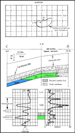
Figures 21-27Meander Belt SedimentationBased on electric log character of readily correlatable interfluve facies (Figures 4, 9, and 10) and electric log character of meander belt facies (point bar, shaly point bar and shale-filled channels) (Figures 3, 12, 15, 16 and 18), the river meander belt associated with entrapment of hydrocarbons at Campbell-Namao Field was outlined (Figure 14). Within the productive portions of the meander belt, it became obvious that the 20-metre-thick reservoir sandstone was highly compartmentalized. The compartments were characterized by marked differences in the thickness of the oil column and marked differences in the subsea elevation of gas-oil and oil-water contacts. Examples of the differences in oil column thickness and differences in the elevation of gas-oil and oil-water contacts are shown on sections G-H and X-X' across and within the meander belt (Figures 14 and 20) and on section J-K along the meander belt (Figures 14 and 19). During development drilling of the Campbell-Namao Field, seismic techniques had not yet been developed to trace the precise location of shale-filled channels or the extent of individual hydrocarbon compartments. Thus, in an attempt to map the extent of individual compartments, groups of wells with essentially the same oil column thickness and the same subsea elevation of gas-oil and oil-water contacts were circumscribed by a shale filled channel. Although this mapping was aided by incorporating the location of 14 boreholes that intersected shale-filled channels, paucity of well control in some parts of the field permits only the approximate shape and extent of some compartments to be outlined. In plan view (Figure 14), the less extensive point-bar sandstone reservoirs are probably remnants of much more extensive point bars which have been transected by successive deeply entrenched channels along the same meander belt, and perhaps closer well control would reveal that the smaller reservoir compartments may be bounded by one or more straight edges or have a crescent shape. For example, extensive point bars and areally small, variously shaped remnants of point bars have been mapped along a meandering portion of the Mississippi River near Vicksburg and Natchez, Mississippi (Concoran et al., 1993). Furthermore, it is recognized that heterogeneity within point bar sandstones could result in compartmentalization of a hydrocarbon-bearing reservoir with differing gas-oil and oil-water contacts within the same point bar (Jordan and Prior, 1992). Thus, some of the smaller compartments shown in Figure 14 may in fact be separated by a shaly facies instead of a true shale-filled channel. The maximum extent of individual compartments (point bars or remnants of point bars) is 518 hectares (2 square miles) (Figures 13 and 14). In the southern part of Figure 14, the meander belt is 3.2 km (two miles) wide. Northward, the meander belt abruptly widens to 5.6-8.0 km (3½ to 5 miles), and that widening is interpreted to be due to avulsion and the establishment of a slightly younger sub-parallel meander belt, as shown in Figure 21. As on modern flood plains, Mannville meandering rivers probably were characterized by periodic channel switching. As a river meanders, natural levees and crevasse splays form during seasonal flooding and overbank flow (Allen, 1965). The levees gradually build up by vertical accretion above the level of the back-swamp or flood plain until such time as conditions become unstable and the river breaks out and excavates a new channel to the sea (avulsion) (Figures 8 and 22). As pointed out by Wood (1989), the initial channel in this process of avulsion is relatively straight. Also, in the case of large rivers, the excavated channel may be very deep. For example, the meandering portion of the Mississippi River at Baton Rouge, Louisiana, has excavated a channel 35 metres deep; i.e., from a surface elevation of 10 metres above sea level (top of the levee) to a depth of 25 metres below sea level (Farrell, 1987). As depicted in Figure 22, as a newly avulsed river begins to meander, it erodes the cutbank in previously deposited sediments. Also, if the amount of sediment in the river system exceeds its carrying capacity, a sandy point bar forms on the convex edge of the meandering channel. As the river continues to erode the cutbank, the river channel moves laterally. At the same time that the cutbank is eroded, the point bar continues to form by lateral accretion and gradually occupies the position of the former channel.
Internal Meander Belt EntrapmentAn examination of cross sections (Figures 19 and 20) and structure contours on top of the Ellerslie Member (Figure 23) show that although there is considerable structural warping of the Ellerslie Member, the main element in hydrocarbon entrapment within the meander belt is stratigraphic control. Structural warping definitely enhances or decreases the pay thickness at individual wells but in general is not a controlling factor in entrapment. Masters (1984) points out that the McMurray oil sands represent an immense anticlinal closure, 150 miles long by 70 miles wide, caused by updip eastward dissolution of thick Middle Devonian salt. He postulates that: (1) the oil sands represent an enormous light gravity oil accumulation that was later biodegraded to its present viscous state, and (2) that the source of the oil was Lower Cretaceous shales and older Mesozoic shales of the deep Alberta basin. In contrast, Stanton (2003, 2004) in a scholarly geochemical treatise concludes that in terms of sheer magnitude, there is insufficient volume of Lower Cretaceous and Jurassic black shale source beds in western Alberta to account for the enormous quantities of heavy oil and bitumen in eastern Alberta. On the other hand, he notes that in the deep basin, foothills and mountains, vast quantities of coal occur within Lower Cretaceous - Jurassic interval. He therefore postulates that most of the aforementioned heavy oil and bitumen represent light gravity oil formed during bituminization of vast quantities of coal source beds, with only a minor portion being derived from the interbedded black shale. Stanton believes that the original light gravity oil followed permeable zones along the pre-Cretaceous unconformity and was later biodegraded. In any case, if originally vast quantities of light gravity oil and gas were squeezed out of deep basin Lower Cretaceous and Jurassic source beds, it follows that all Lower Cretaceous stratigraphic and structural traps along the migration path were filled to spill point. Because the gas caps at Campbell-Namao Field are invariably oil stained, it is interpreted that light gravity oil first entered all the traps and filled them to spill point. Some of the natural gas that later entered the traps may have been from local sources moving into the point bar sandstones from various directions and spilling oil updip. Thus, the pattern of oil and gas accumulation shown in Figure 19 does not conform with the differential entrapment scheme outlined by Gussow (1954). It is interesting to note that the thickest oil column shown in Figure 19 at the 9-26 well did not have an original gas cap and is located in a synclinal structure as mapped on the top of the Ellerslie Member (Figure 23).
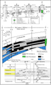
External Meander Belt EntrapmentThe curved shape of the meander belt shown in Figure 14 is also a controlling factor in truncation type stratigraphic traps illustrated in Figure 25. Because of the curvature of the downdip (southwestern) edge of the meander belt, deeply entrenched shale-filled channels are interpreted to have caused both updip and lateral stratigraphic entrapment within two sheet sandstones (the Acheson Sandstone and the next underlying sandstone) of the interfluve facies. A stratigraphic trap within the Peavey Sandstone, similar to that shown in Figure 9, overlies the two truncation type traps (Figure 25). As shown in Figures 23 and 25, the oil columns in the Peavey and Acheson sandstones extends 4 km (2 ½ miles) down-dip from their structurally highest point and cover an area of 2331 hectares (9 square miles). In an early paper on the Campbell oil pool, Klaui (1953) numbered the five productive sandstones from the top downward and his numbering system is shown in Figure 25. Thus, only Klaui’s number 2 and 3 sandstones are interpreted to be truncated by a shale-filled channel. Traps within the number 4 and 5 sandstones are interpreted to be stratigraphic traps caused by up-dip shale-out of the productive sandstone similar to the number 1 (Peavey) sandstone. The closed low structure on the eroded top of the Wabamun Formation, marked by the -470 and -480m subsea contours near the center of Figure 7, is interpreted to be a karst structure caused by collapse of the roof of a cave within the Wabamun Formation after the Ellerslie Member was deposited. For example, contours on top of the Ellerslie Member (Figure 23) reveal a distinct syncline separating the two Peavey Sandstone gas-caps and that syncline coincides with the interpreted collapse structure on the eroded top of the Wabamun Formation. In central Alberta, where the Wabamun Formation is truncated by pre-Cretaceous erosion, there is local evidence of karsting or open caverns at or below the eroded top of the Wabamun. For example, in Wabamun core studies associated with his paper, Andrichuk (1960) described dolomite solution breccias with waxy green claystone matrix, tens of metres thick, occurring at the eroded top of the Wabamun at Union Storvick 13-28-46-17 W4M. Also, Glaister (pers. comm., 2003) states that in 1954, at Imperial Rosalind 8-9-44-17 W4M, after drilling a short distance into the Wabamun with no problems, the bit suddenly dropped about 7 metres and circulation was lost for over 2 months before the well was abandoned. Drilling then commenced immediately on the adjoining Lsd 9 and total depth at that location was reached in the Beaverhill Lake Formation without any Wabamun lost circulation problems.
Structural EntrapmentIn upper Ellerslie interfluve areas near Edmonton, numerous anticlinal gas and oil accumulations occur in the upper part of the Ellerslie Member. In the thin sandstone beds that characterize the interfluve areas, only slight structural closure is required to trap hydrocarbons, and in some cases, pay zones are stacked. Drillstem tests of those thin sandstone beds commonly yielded up to 28.2 x 10³ m3 (1 million cubic feet) of gas per day with very little pressure drop in a one hour test. However, due to the typically small areal extent of the traps, such gas wells often water-out after only minor production (Figure 26). As illustrated in Figure 27, minor upper Ellerslie Member anticlinal structures can occur due to:
As shown in Figure 19, a 4-metre (13-feet)-thick upper Ellerslie gas accumulation at the 14-6 well is interpreted as due to local structural warping of a mainly water-bearing point bar. Like many upper Ellerslie structural accumulations in interfluve areas, the 14-6 well, after recording a flow of 27,000 m3/day (959 Mcf/d) on drillstem test, produced only 256 x 103m3 (9.09 MMcf) gas before being abandoned.
ConclusionsIn central Alberta, upper Ellerslie meander belts are mapped from electric logs with relatively sparse well control. In exploratory drilling along these meander belts, hydrocarbon reserves similar in size to those in productive point bars at Campbell-Namao Field (i.e., 5.8 Bcf gas and 258,000 bbl. oil per square mile) can be expected. Moreover, if “bright spot” seismic technology to map upper Ellerslie Member gas accumulations (with or without associated oil columns) can be improved, it should be possible to attain almost 100% success in exploratory drilling along known upper Ellerslie meander belts. The exploration procedure outlined herein applies to meander belts of various ages world-wide provided that (1) the point bar sandstones retain their porosity and permeability, (2) source rocks at sufficient depth and temperature are available to generate hydrocarbons, and (3) the point bar sandstones have a roof-seal.
Allen, J.R.L., 1965, A review of the origin and characteristics of recent alluvial sediments: Sedimentology, v.5, p. 89-191. Andrichuk, John M., 1960, Facies analysis of Upper Devonian Wabamun Group in west central Alberta, Canada: AAPG Bulletin, v. 44, p. 1651-1681. Arnot, R.W.C., Zaitlin, B.A., and Potocki, D.J., 2000, Geological controls on reservoir distribution in the Lower Cretaceous Basal Quartz, Chin Coulee-Horsefly Lake area, south-central Alberta: Bulletin of Canadian Petroleum Geology, v. 48, p. 212-229. Banerjee, I., and Davies, E.H., 1988, An integrated lithostratigraphic and palynostratigraphic study of the Ostracode zone and adjacent strata in the Edmonton embayment, central Alberta, in Sequences, Stratigraphy, Sedimentology: Surface and Subsurface, D.P. James and D.A. Leckie, eds., Canadian Society of Petroleum Geologists Memoir 15, p. 261-274. Bernard, H.A., Major, C.F., Parrott, B.S., and Le Blanc, R.J., 1970, Recent sediments of southeast Texas, a field guide to the Brazos alluvial and deltaic plains and the Galveston barrier island complex: Guidebook II, Bureau of Economic Geology, The University of Texas at Austin. Cant, D.G., 1992, Subsurface facies analysis, in Facies Models, Response to Sea Level Change, R.G. Walker and N.P. James, eds., Geological Association of Canada, p. 27-45. Cederwall, D.A., 1989, The Lower Cretaceous, in Geophysical Atlas of Western Canadian Hydrocarbon Pools, N.L. Anderson, L.V. Hills, and D.A. Cederwall, eds., Canadian Society of Exploration Geophysicists and Canadian Society of Petroleum Geologists, p. 217-281. Coleman, J.M., and Prior, D.B., 1982, Deltaic environments of deposition, in Sandstone Depositional Environments, P.A. Scholle and D. Spearing, eds., AAPG Memoir 31, p. 139-178. Collinson, J.D., 1978, Vertical sequence and sand body shape in alluvial sequences, in Fluvial Sedimentology, A.D. Miall, ed., Canadian Society of Petroleum Geologists Memoir 5, p. 577-586. Corcoran, M.K., Harrelson, D., Albertson, P., and Saucier, R.T., 1993, Guidebook, Geological and cultural excursion Jackson, Mississippi to Natchez, Mississippi: AAPG 1993 Annual Meeting, published by New Orleans Geological Society, 61p. Edie, R.W., 1955, The inclined oil-water contact at the Joarcam Field: Journal of the Alberta Society of Petroleum Geologists, v. 3, no. 7, p. 99-103. Edie, R.W., and Andrichuk, J.M., 2003, Meander belt entrapment of hydrocarbons at Saddle Lake, Alberta and an untested in situ combustion scheme for recovery of heavy oil: Bulletin of Canadian Petroleum Geology, v.51, p.253 – 274. Ethridge, F.G., Skelly, R.L. and Bristow, C.S. 1999, Avulsion and crevassing in the sandy, braided Niobrara River: complex response to base-level rise and aggradation, in Fluvial Sedimentology VI, N.D. Smith and J.J. Rogers, eds., International Association of Sedimentologists Special Publication 28, p. 179-191. Farrel, K.M., 1987, Sedimentology and facies architecture of overbank deposits of the Mississippi River region, Louisiana, in Recent Developments in Fluvial Sedimentology, F.G. Ethbridge, R.M., Flores, and M.D. Harvey, eds., Society of Economic Paleontologists and Mineralogists Special Publication no. 39, p. 111-120. Flach, P.D., and Mossop, G.D., 1985, Depositional environments of Lower Cretaceous McMurray Formation, Athabasca Oil Sands, Alberta, American Association of Petroleum Geologists Bulletin, v.69 p. 1195 – 1207. Glaister, R.P., 1959, Lower Cretaceous of southern Alberta and adjoining areas: AAPG Bulletin, v. 43 p. 590-640. Gussow, W.C., 1954, Differential entrapment of oil and gas: a fundamental principle: AAPG Bulletin, v. 38 p. 816-853. Hayes, M.O., 1989, Modern clastic depositional environments, South Carolina: 28th International Geological Congress Field Trip Guidebook T371, American Geophysical Union, Washington, D.C. Holmden, C., Muehlenbachs, K, and Creaser, R.A., 1997, Depositional environments of the Early Cretaceous Ostracode zone: paleohydrologic constraints from O, C and Sr. isotopes, in Petroleum Geology of the Cretaceous Mannville Group, Western Canada, S.G. Pemberton and D.P. James, eds., Canadian Society of Petroleum Geologists Memoir 18, p. 77-92. Hunt, C.W., 1950, Preliminary report on Whitemud Oil Field: AAPG Bulletin, v. 34, p. 1795-801. Jackson, K.E., and Bourns, G.E., 1968, Alexander Gas Field, Alberta, Canada, in Natural Gases of North America, Part 2. Natural Gases in Rocks of Mesozoic Age, AAPG Memoir 9, v. 1, p. 705-712. Jordan, D.W., and Prior, W.A. 1992. Hierarchical levels of heterogeneity in a Mississippi River meander belt and application to reservoir systems: AAPG Bulletin, v.76, p.1601-1624. Karvonen, R.L., 1989, The Ostracode Member east-central Alberta: An example of an estuarine valley fill deposit, in Modern and Ancient Examples of Clastic Tidal Deposits – A Core and Peel Workshop, G.E. Reinson, ed., Canadian Society of Petroleum Geologists, Second International Research Symposium on Clastic Tidal Deposits, Aug. 22 – 25, Calgary, p. 105-116. Karvonen, R.L., and Pemberton, S.G., 1997, Sedimentology, ichnology and stratigraphy of the Ostracode Member (Lower Cretaceous) in the Jenner – Suffield area, southeast Alberta, in Petroleum Geology of the Cretaceous Mannville Group, Western Canada, S.G. Pemberton and D.P. James, eds., Canadian Society of Petroleum Geologists Memoir 18, p. 103-123. Klaui, P., 1953, Basal Lower Cretaceous accumulations in Alberta with special reference to the Campbell Pool: The Petroleum Engineer, February, p. B-6 – B-10. Labute, G.J., and Gretener, P.E., 1969, Differential compaction around a Leduc reef, Wizard Lake area, Alberta: Bulletin of Canadian Petroleum Geology, v. 17, p. 304-325. Loranger, D.M., 1951, Useful Blairmore microfossil zone in central and southern Alberta, Canada: AAPG Bulletin, v. 35, p.2348-2367. Mason, R.J., 1969a, Alexander Field, Basal Quartz sandstone, in Gas Fields of Alberta, Alberta Society of Petroleum Geologists, p. 46-47. Mason, R.J., 1969b, St. Albert – Big Lake Field, Ostracode sandstone, in Gas Fields of Alberta, Alberta Society of Petroleum Geologists, p. 304-305. Masters, J.A., 1984, Lower Cretaceous oil and gas in western Canada, in Elmworth – Case Study of a Deep Basin Gas Field, J.A. Masters, ed., AAPG Memoir 38, p. 1-47. Matheson, J.E. 1988, The Upper Mannville tidal creek and incised fluvial channel reservoirs at the Fort Kent Thermal Project of east-central Alberta, in Sequences, Stratigraphy, Sedimentology: Surface and Subsurface, D.P. James and D.A. Leckie, eds., Canadian Society of Petroleum Geologists Memoir 15, p. 331-350. McLean, J.R., and Wall, J.H., 1981, The Early Cretaceous Moosebar sea in Alberta: Bulletin of Canadian Petroleum Geology, v. 29, p. 334-377. Nummedal, D., and Swift D.J.P., 1987, Transgressive stratigraphy at sequence – bounding unconformities: some principles derived from Holocene and Cretaceous examples, in Sea-Level Fluctuation and Coastal Evolution: Society of Economic Paleontologists and Mineralogists Special Publication no. 41, p. 241-260. Rudkin, A.R., 1964, The Lower Cretaceous, in Geological History of Western Canada, R.G. McCrossan, and R.P. Glaister, eds., Alberta Society of Petroleum Geologists, p. 156-168. Smith, D.G., 1987, Meandering river point bar lithofacies models: modern and ancient examples compared, in Recent Developments in Fluvial Sedimentology, F.G. Ethridge, R.M. Flores, and M.D. Harvey, eds., Society of Economic Paleontologists and Mineralogists, Special Publication no. 39, p. 83-91. Stanton, M.S., 2003, Origin of the Lower Cretaceous heavy oils of Alberta: unpublished manuscript (10 pages plus 17 figures), on file at the Gallagher Library, University of Calgary, Calgary, Alberta. Stanton, M.S., 2004, Origin of the Lower Cretaceous heavy oils (“tar sands”) of Alberta: Search and Discovery Article #10071 (2004) (http://www.searchanddiscovery.net/documents/2004/stanton/index.htm). Strobl, R.S., Muwais, W.K., Wightman, D.M., Cotterill, D.K., and Yuan, L.P., 1997, Application of outcrop analogues and detailed reservoir characterization to the AOSTRA Underground Test Facility, McMurray Formation, northeastern Alberta, in Petroleum Geology of the Cretaceous Mannville Group, Western Canada, S.G. Pemberton and D.P. James, eds., Canadian Society of Petroleum Geologists Memoir 18, p. 375-391. Thomas, R.G., Smith , D.G., Wood, J.M., Visser, J., Calverley-Range, E.A., and Koster, E.H., 1987, Inclined heterolithic stratification - terminology, description, interpretation and significance: Sedimentary Geology, v. 53, p. 123-179. Walker. R.G., and Cant, D.J., 1984, Sandy fluvial systems, in Facies Models, second edition, Geoscience Canada, Reprint Series 1, R.G. Walker, ed., Geological Association of Canada, p. 71-89. Wightman, D.M., and Pemberton S.G., 1997, The Lower Cretaceous (Aptian) McMurray Formation: An overview of the Fort McMurray area, Northeastern Alberta, in Petroleum Geology of the Cretaceous Mannville Group, Western Canada, S.G. Pemberton and D.P. James, eds., Canadian Society of Petroleum Geologists Memoir 18, p. 312-344. Williams, G. D., 1963, The Mannville Group (Lower Cretaceous) of central Alberta: Bulletin of Canadian Petroleum Geology, v. 11, p. 350-368. Williams, G.D., and Stelck, C.R., 1975, Speculations on the Cretaceous paleogeography of North America, in The Cretaceous System in the Western Interior of North America, The Geological Association of Canada Special Paper no. 13, p. 1-20. Wood, J.M., 1989, Alluvial architecture of the Upper Cretaceous Judith River Formation, Dinosaur Provincial Park, Alberta, Canada: Bulletin of Canadian Petroleum Geology, v. 37, no. 2, p. 169-181.
The authors thank Oscar A. Erdman, R. Perry Glaister, Grant D. Mossop, and Gordon D. Williams for reading the manuscript and offering suggestions for improvement. Editor Tim de Freitas and Associate Editor James M. Wood, Canadian Society of Petroleum Geologists, also offered many helpful suggestions for improvement of the text and figures. The writers are also grateful to Regina Shedd at the Gallagher Library, University of Calgary, for assistance in obtaining important geological references, and to David G. Sargent, for computer drafting of the figures. |


