![]() Click
to view presentation in PDF format.
Click
to view presentation in PDF format.
Ghawar: The Anatomy of the World's Largest Oil Field*
By
Abdulkader M. Afifi1
Search and Discovery Article #20026 (2005)
Posted January 25, 2005
*Adapted from AAPG Distinguished Lecture, 2004. Online adaptation of the presentation of "Paleozoic Hydrocarbon Habitat in the Arabian Plate," the other AAPG Distinguished Lecture presented by the author in 2004, is also posted on Search and Discovery.
1Saudi Aramco, Dhahran, Saudi Arabia ([email protected])
Abstract
Aramco initially discovered oil in Ghawar in 1948, based on surface mapping and shallow structure drilling. Ghawar is a large north-trending anticlinal structure, some 250 kilometers long and 30 kilometers wide. It is a drape fold over a basement horst, which grew initially during the Carboniferous Hercynian deformation and was reactivated episodically, particularly during the Late Cretaceous. In detail, the deep structure consists of several en echelon horst blocks that probably formed in response to right-lateral transpression. The bounding faults have throws exceeding 3000 feet at the Silurian level but terminate within the Triassic section. The episodic structural growth influenced sedimentation of the Permo-Carboniferous sandstone reservoirs, which onlap the structure and the Jurassic and Permian carbonate reservoirs, which accumulated in shoals above structural culminations.
The main oil reservoir is the Upper Jurassic Arab-D limestone, which improves upward from mudstone to skeletal-oolitic grainstone, reflecting successive upward-shoaling cycles. The excellent reservoir quality is due to the preservation of the primary porosity, the enhancement of permeability, and the presence of fractures in the deeper and tighter parts. The oil was sourced exclusively from Jurassic organic-rich mudstones and is effectively sealed beneath massive anhydrite. The general absence of faults at the Arab-D level maintained seal integrity. Current production is almost 5 million barrels per day under peripheral water injection. The southernmost part of the field remains under development, with a final increment of 300,000 barrels per day on stream in 2006.
In addition to oil, Ghawar contains large reserves of non-associated gas in the deeper Paleozoic reservoirs, sourced from Silurian shales and trapped in Permian, Permo-Carboniferous and Devonian reservoirs at depths of 10,000-14,000 feet.
The main gas reservoirs are in the Khuff A, B, and C carbonates of Late Permian age. Each consists of transgressive grainstones and packstones, sealed by regressive supra- and intertidal mudstone and anhydrite. The Khuff carbonates are highly cyclical and have undergone extensive diagenesis, resulting in variable reservoir and gas quality. The migration of gas into the Khuff probably occurred along the western bounding fault of Ghawar, which propagated upward through the Khuff during the Cretaceous reactivation.
In addition, sweet gas is trapped structurally and stratigraphically in the Permo-Carboniferous Unayzah sandstones, which onlap the ancestral Ghawar highlands from the south. The Unayzah consists of eolian, fluvial, and lacustrine clastics whose reservoir quality is highly variable due to facies changes and quartz cementation. In 1994, an exploration well drilled on the east flank of Ghawar discovered sweet gas in Devonian sandstones in a fault-unconformity truncation trap. Since then, exploration of Paleozoic targets has added 15 new discoveries in and around Ghawar. Development has increased daily Ghawar production capacity to 8 billion cubic feet. The key challenge to gas exploration and development has been the prediction of porosity using geologic models and 3D seismic data.
|
|
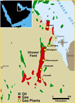
Ghawar Field: Basic Information Size: 174 x 16 miles (280 x 26 kilometers); area: ~ 2050 mi2 (~ 1.3 million acres) (Figure 1).Size comparison: Length of Ghawar field, of 174 miles, is equivalent to 70% of the north-south distance across Louisiana (Figure 2).Oil discovery: 1948.On stream: 1951.Peripheral water injection: 1965.Oil production: ~ 5 million B/D from Jurassic Arab-D.Gas production: 8 billion SCF/D (associated gas: ~ 2 BSDFD, non-associated gas: ~ 6 BSCFD from Paleozoic reservoirs).History of DiscoveriesFigure Captions (3-7)
OilOil was discovered in 1948 in the northern part (one-fourth) of the structure at 'Ain Dar. Subsequent discoveries were made at Haradh (in the southern part) in 1949, at 'Uthmanijah north of the east-west midline in 1951, at Shedgum in the northeast in 1952, and Hawiyah south of the east-west midline in 1953 (Figure 3).Field mapping (Figure 4) and innovative shallow drilling (Figure 5) for structural control were the means by which the Ghawar structure was delineated originally. The changes in delineation during development from 1952 to 1955 is shown in Figure 6.GasGas was discovered in the Permian Khuff carbonate in 1971 in the southern third of the field (Figure 7). In 1975, the second Khuff discovery was made in the northernmost part of the field; to the east the third discovery (in the Khuff and Devonian Jauf) was made in 1980. It was followed, also in 1980, by the fourth discovery, some 15 miles to the south, in the Khuff. The fifth discovery, east of the first, was made in the Permo-Carboniferous Unayzah Sandstone in 1982. The sixth was the east-flank-play discovery in the Devonian Jauf Sandstone (see Figure 28).
Structure
The regional setting of Ghawar is shown by the regional east-west cross-section in Figure 8. As a basement horst, it is the most prominent structure on the west flank of the foredeep basin. Other drape anticlines overlying basement faults are present updip from Ghawar and possibly salt-related structures are present to the east. In detail, as shown by the seismic section in Figure 9, the dominant basement fault is reverse, probably resulting from transpression.Deep Ghawar structure, as depicted in Figure 10 by Silurian dip magnitude and Permian-Silurian isochron, is characterized by eroded sections in the southern and northern paleo-culminations. Although the fault zones on the west and east show some areal differences, they are approximately parallel.In terms of structural style, Ghawar has been compared to Laramide uplifts of the Rocky Mountains (Figure 11). The principal compressive stress is thought to have been horizontal and in a general northeast-southwest direction. This stress field was expressed by right-lateral fault movement to form the Ghawar structure (Figure 12).
Figure Captions (13-17)
Jurassic Arab-DThe main oil reservoir of Ghawar is the Upper Jurassic Arab-D limestone (Figures 13, 14, 15, and 16). Regionally the depositional setting for the southern part of the structure was an intrashelf basin, whereas the northern part was part of a platform to shoal (Figure 13). It is some 400 feet thick, and the various reservoir zones that have been recognized (Figure 16) probably correspond to upward-shoaling cycles. In these cycles there is corresponding upward improvement of reservoir quality. The type of carbonate changes upward from mudstone to rudstone to wackestone, to grainstone (commonly ooid-coated) (Figure 15).Oil production has remained fairly constant at approximately 5 million barrels per day from 1993 to 2003 (Figure 17). The water-cut increased from 26% in 1993 to 37% in 1999, but it decreased afterward to 33% in 2003.
Gas Reservoirs
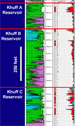
Permian KhuffPermian Khuff carbonate is one of three major gas-producing Paleozoic stratigraphic units (Figure 18) and the lowermost producing carbonate in the field. With representative thickness of approximately 900 feet, it consists of three stacked reservoirs, with separate gas-water contacts (Figure 19). Khuff reservoir facies include burrowed, subtidal dolomite, deposited in shallow subtidal environment, dolomite with low-angle cross-beds (storm washout), and dolomitic limestone (tidal bar / shoal complex) (Figure 20). The first represents a microcrystalline dolomite facies; the last, oomoldic facies. Porosity in Khuff C shows a good correlation with acoustic impedance (Figure 21).Temperature in Khuff reservoirs generally increases northward. H2S content is lowest in the south and in the northwesternmost part of the field; it is more than 5% in an elongated area north of the central part of the field and in a more restricted area in the northeasternmost part (Figure 22). The gas charge was lateral, from the north (Figure 23); migration into the Khuff was probably along the bounding fault on the west.The source of the gas is Silurian Qusaiba hot shale. Seals include intra-Khuff dolomite and anhydrite and overlying Triassic shale.
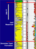
Permo-Carboniferous Unayzah SandstoneThe Unayzah Sandstone, which may be more than 700 feet thick, is divided into two reservoirs (A and B) (Figure 24). It consists of eolian, fluvial, and lacustrine deposits (Figure 25). The cross-bedded eolian facies represents the best reservoir type. The source is Silurian shales; the charge is from below. The seals are Permian Khuff basal shale and anhydrite. Devonian Jauf SandstoneWhere fully developed, the Jauf reservoir is more than 600 feet thick (Figure 26). It was deposited in estuarine and coastal environments. At depths of approximately 14,000 feet, the sandstone shows both favorable and adverse effects of diagenesis (Figure 27). In the former case, illite grain coatings preserve porosity; in the latter case, quartz cementation may be extensive.The source is Silurian shales. The seals are intraformational shale or basal Khuff shale and anhydrite. The charge is from below.In the 1994 discovery (Figure 7), the Jauff produces gas from a fault-unconformity trap on the east flank of Ghawar (Figure 28).Summary
AcknowledgementsAppreciation and acknowledgments are expressed to Dave Alexander, Mohamed Ameen, Scott Amos, Dave Cantrell, Greg Gregory, Chris Heine, Wyn Hughes, Tom Keith, Maher Al-Marhoon, John Melvin, Ali Al-Muallem, Abdulla Al-Naim, Han Sibon, Aus Al-Tawil, Kamal Al-Yahya, and Hong Bin Xiao.ReferenceMurris, R.J., 1980, Middle East: Stratigraphic evolution and oil habitat: AAPG Bulletin v. 64, p. 598-618.
About the AuthorDr. Abdulkader M. Afifi was educated in Saudi Arabia (B.S., University of Petroleum and Minerals, 1977) and in the United States (M.S. Colorado School of Mines. 1981; Ph.D., University of Michigan, 1990). His experience includes: 1980-86 = U.S. Geological Survey Mission, Saudi Arabia; Geological Mapping, Geochemical and Stable Isotopic Studies of the Mahd Adh Dhahab Gold District. 1991-Present - Saudi Aramco, Dhahran, Saudi Arabia. Several technical and supervisory positions in the Exploration Organization including Chief Explorationist and Chief Geologist. Currently, Senior Geological Consultant, Upstream Ventures Department. |