|
uAbstract
uFigure
captions (1-3)
uIntroduction
u Analog Analog modeling
tExperimental
method
tResults
sFigure
captions (4-6)
sOrthogonal
rift models
sOblique
rift models
sFigure
captions (7-9)
sOffset
rift models
uFigure
captions (10-16)
uDiscussion
tAnalog
models
tComparisons
with natural examples
sOrthogonal
rifts
sOblique
& offset rifts
uConclusions
uReferences
uAuthors
uAcknowledgements
uAbstract
uFigure
captions (1-3)
uIntroduction
uAnalog
modeling
tExperimental
method
tResults
sFigure
captions (4-6)
sOrthogonal
rift models
sOblique
rift models
sFigure
captions (7-9)
sOffset
rift models
uFigure
captions (10-16)
uDiscussion
tAnalog
models
tComparisons
with natural examples
sOrthogonal
rifts
sOblique
& offset rifts
uConclusions
uReferences
uAuthors
uAcknowledgements
|
Figure Captions (1-3)
 Figure
1. Conceptual models of displacement transfer in rift systems. (a) Synoptic
model of a low-strain intracontinental rift with along-axis segmentation.
Individual half grabens are separated by soft-linked accommodation zones formed
by overlapping fault segments. (b) Synoptic model of hard-linked, strike-slip,
rift transfer-fault system. Figure
1. Conceptual models of displacement transfer in rift systems. (a) Synoptic
model of a low-strain intracontinental rift with along-axis segmentation.
Individual half grabens are separated by soft-linked accommodation zones formed
by overlapping fault segments. (b) Synoptic model of hard-linked, strike-slip,
rift transfer-fault system.
 Figure
2. Analog modeling rig. (a) Plan view showing baseplate orientation with respect
to the extension direction. (b) Cross-section view of deformation rig. (c)
Baseplate geometries used in this study: 90 degrees
(orthogonal models),
60 degrees,
45 degrees (oblique) rifts and offset rifts. Figure
2. Analog modeling rig. (a) Plan view showing baseplate orientation with respect
to the extension direction. (b) Cross-section view of deformation rig. (c)
Baseplate geometries used in this study: 90 degrees
(orthogonal models),
60 degrees,
45 degrees (oblique) rifts and offset rifts.
 Figure
3. Scaling parameters for the simulation of brittle deformation of sedimentary
rocks in the upper crust. (a) Detachment; (b) brittle-plastic transition. Figure
3. Scaling parameters for the simulation of brittle deformation of sedimentary
rocks in the upper crust. (a) Detachment; (b) brittle-plastic transition.
Introduction
Many natural rift systems
display along-strike changes in extensional fault polarities and in offset
grabens and depocenters along the rift axis (cf. Bally, 1981; Gibbs, 1983, 1984,
1987; Bosworth, 1985, 1994; Lister et al., 1986; Rosendahl et al., 1986;
Etheridge et al., 1987; Rosendahl, 1987; Ebinger, 1989a, b; Morley et al., 1990,
1994; Nelson et al., 1992; Faulds and Varga, 1998). This segmentation in rift
systems characteristically occurs every 50-150 km along the rift axis (Rosendahl
et al., 1986; Patton et al., 1994; Hayward and Ebinger, 1996); increased
extension and continental separation may ultimately lead to segmentation along
conjugate passive margins (cf. Karner and Driscoll, 1999). Two end-member models
(Figure 1) have been proposed to account for these changes in fault polarities
and offset depocenters: (1) the hard-linked strike-slip or oblique-slip transfer
fault model (cf. Bally, 1981; Gibbs, 1983, 1984; Lister et al., 1986) and (2)
the soft-linked accommodation zone model of distributed faulting without
distinct cross faults or transfer faults (cf. Bosworth, 1985, Rosendahl et al.,
1986; Morley et al., 1990; Morley, 1994; Moustafa, 1997; Faulds and Varga,
1998). The detailed structure and kinematic evolution of these changes on rift
polarities and on the development of accommodation zones, however, are poorly
understood.
Scaled analog sandbox models have
proved to be powerful tools for simulating the development of extensional
structures in rift systems (e.g., Cloos, 1968; Horsfield, 1977, 1980; Faugere
and Brun, 1984; Withjack and Jamison, 1986; Serra and Nelson, 1989; McClay,
1990a, b; Tron and Brun, 1991; McClay and White, 1995). This article summarizes
the results of a new series of three-dimensional (3-D) sandbox models of
orthogonal, oblique, and offset rift systems in which rift segmentation and
discrete accommodation zones are well developed. These model results are
compared with natural intracontinental rift systems.
Analog Modeling
Experimental Method
The experiments were
carried out in a deformation rig 120 x 60 x 7.5 cm in size (Figure
2). The models consisted of a 7.5 cm-thick sandpack formed by mechanically
sieving 2-3 mm-thick layers of white and colored dry, quartz sand (average grain
size 100 µm) on top of a basal detachment formed by a 10-15 cm-wide rubber sheet
fixed between two aluminum end sheets. The rubber sheet was either parallel
sided or offset by discrete basal transfer faults (Figure
2c). The baseplate axes were oriented at angles of from 90 degrees
(orthogonal) to 45 degrees (oblique) to the extension direction. Deformation was
achieved by moving both of the end walls with a motor-driven worm screw at a
constant displacement rate of 4.16 x 10⁻³ cm/sec (Figure
2). The models were extended in 0.25 cm increments to a maximum of 7.5 cm,
measured orthogonally to the rift axis; the top surfaces were recorded by 35 mm
photography. Oblique rift models were extended to a maximum of 10.65 cm parallel
to the long axis of the deformation apparatus to achieve the required 7.5 cm
stretching of the rubber basesheet (Figure
2). After each 2 cm of deformation, the accommodation space was infilled
with alternating layers of white and red sand to simulate synrift sedimentation.
The quartz sand has a linear Navier-Coulomb behavior that has an angle of
friction of 31 degrees (McClay, 1990b). The models described in this article are
scaled such that they simulate brittle deformation of a sedimentary sequence
between 1 and 10 km in thickness (Figure
3) (cf. McClay, 1990a). The models for each baseplate geometry investigated
were repeated at least twice to ensure reproducibility and to allow for both
horizontal and vertical sectioning.
Results
Representative results
from orthogonal, oblique, and offset rift models are illustrated in Figures 4-9.
Top photographs, line diagram interpretations, and serial vertical sections are
presented for each example.
Figure Captions (4-6)
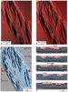
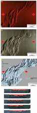
 Figure
4. Analog model E 350: Orthogonal Rift. (a) Overhead view of analog model after
4 cm extension. Illumination is from the left. (b) Overhead view of analog model
after 7.5 cm extension. Illumination is from the left. (c) Line diagram
interpretation of the surface fault pattern at the end of extension. Dark bands
are faults dipping to the right, and light bands are faults dipping to the left.
The blue shading marks the stretched rubber sheet at the base of the model. (d)
Serial sections through the orthogonal rift model. Synkinematic strata are the
red and white layers at the top of the grabens on each side of the central
intrarift horst block. Location of sections is indicated in (c). Figure
4. Analog model E 350: Orthogonal Rift. (a) Overhead view of analog model after
4 cm extension. Illumination is from the left. (b) Overhead view of analog model
after 7.5 cm extension. Illumination is from the left. (c) Line diagram
interpretation of the surface fault pattern at the end of extension. Dark bands
are faults dipping to the right, and light bands are faults dipping to the left.
The blue shading marks the stretched rubber sheet at the base of the model. (d)
Serial sections through the orthogonal rift model. Synkinematic strata are the
red and white layers at the top of the grabens on each side of the central
intrarift horst block. Location of sections is indicated in (c).
Click here for sequence
of Figure 4a, b, c.
Click here for sequence of sections shown in 4d.
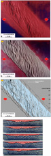
 Figure
5. Analog model E 351: 60 degrees Oblique Rift. (a) Overhead view of analog
model after 4 cm extension. Illumination is from the left. (b) Overhead view of
analog model after 8.65 cm extension (50% stretching at the base of the model).
Illumination is from the left. (c) Line diagram interpretation of the surface
fault pattern at the end of extension. Dark bands are faults dipping to the
right, and light bands are faults dipping to the left. The blue shading marks
the stretched rubber sheet at the base of the model. (d) Serial sections through
the oblique rift model. Synkinematic strata are the red and white layers at the
top of the grabens on each side of the central intrarift horst block. Location
of sections is indicated in (c). Figure
5. Analog model E 351: 60 degrees Oblique Rift. (a) Overhead view of analog
model after 4 cm extension. Illumination is from the left. (b) Overhead view of
analog model after 8.65 cm extension (50% stretching at the base of the model).
Illumination is from the left. (c) Line diagram interpretation of the surface
fault pattern at the end of extension. Dark bands are faults dipping to the
right, and light bands are faults dipping to the left. The blue shading marks
the stretched rubber sheet at the base of the model. (d) Serial sections through
the oblique rift model. Synkinematic strata are the red and white layers at the
top of the grabens on each side of the central intrarift horst block. Location
of sections is indicated in (c).
Click here for sequence
of Figure 5a, b, c. Click
here for sequence of sections shown in 5d.
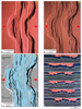
 Figure
6. Analog model E 352: 45 degrees Oblique Rift. (a) Overhead view of analog
model after 4 cm extension. Illumination is from the left. (b) Overhead view of
analog model after 10.6 cm extension (50% stretching at the base of the model).
Illumination is from the left. Line diagram interpretation of the surface fault
pattern at the end of extension. Dark bands are faults dipping to the right, and
light bands are faults dipping to the left. The blue shading marks the stretched
rubber sheet at the base of the model. (d) Serial sections through the oblique
rift model. Synkinematic strata are the lighter layers at the top of the grabens
on each side of the central intrarift horst block. Location of sections is
indicated in (c). Figure
6. Analog model E 352: 45 degrees Oblique Rift. (a) Overhead view of analog
model after 4 cm extension. Illumination is from the left. (b) Overhead view of
analog model after 10.6 cm extension (50% stretching at the base of the model).
Illumination is from the left. Line diagram interpretation of the surface fault
pattern at the end of extension. Dark bands are faults dipping to the right, and
light bands are faults dipping to the left. The blue shading marks the stretched
rubber sheet at the base of the model. (d) Serial sections through the oblique
rift model. Synkinematic strata are the lighter layers at the top of the grabens
on each side of the central intrarift horst block. Location of sections is
indicated in (c).
Click here for sequence of Figure 6a, b, c.
Click here for sequence of sections shown in 6d.
Return
to top.
Orthogonal Rift Models
In orthogonal rift
models, where the underlying zone of basement stretching was oriented 90 degrees
to the extension direction, the early stages of deformation were characterized
by long, linear, extensional faults that formed as a result of along-strike
linkage of initially smaller linear-fault segments (Figure
4a). Two long rift-border faults were well developed by 4 cm of extension,
together with an intrarift fault system that defined a central horst block and
two linear graben systems on each side of it (Figure
4a). Using increased extension to 50% stretching at the base of the model,
individual extensional faults increased their displacement, and extension tended
to focus inward to the centers of each graben system (Figure
4b). The line diagram of
Figure 4c shows the dominant fault systems that have a characteristic switch
in fault dip (polarity) across the model. All faults developed at high angles
(near 90 degrees) to the extension direction. Serial cross sections through the
completed model show the symmetrical nature of the rift system, its cylindricity
along strike, and grabens that developed adjacent to each border fault and the
central horst block (Figure
4d). Individual faults show kinks along their traces (Figure
4a, b, c) where initially separate segments have linked. Overlap zones
between like-dipping faults form relay ramps (Figure
4c), but no accommodation zones or strike-slip transfer faults were
developed in these orthogonal rift models.
Oblique Rift Models
In contrast to the
orthogonal rift models, oblique rift experiments were characterized by strongly
segmented fault systems and offset-basin depocenters in the rift (Figures
5,
6). The 60 degrees oblique model (Figure
5) initially developed arrays of intrarift fault systems oriented at high
angles to the extension vector, and rift margins were formed by individual, en
echelon fault segments. In part these were formed by the tips of major intrarift
fault segments that curved into parallelism with the basement structural grain (Figure
5a). The intrarift fault arrays formed distinct, offset subbasins that
developed on each side of the central rift axis. Using increased extension to
50% stretching at the base of the model, individual segments of the rift-border
faults propagated along strike, breached the relay ramps, and linked, forming a
semicontinuous rift-border fault system (Figure
5b). The intrarift faults increased their displacement and propagated along
strike, forming accommodation zones where groups of like-dipping faults met
groups of oppositely dipping faults (Figure
5b). Here, the tips of the opposing fault sets interlocked, producing a
localized zone of conjugate faults commonly displaying divergent tips (Figure
5b). No strike-slip or oblique-slip transfer faults developed (Figure
5c). The along-strike changes in the subbasins and in the senses of fault
dip are shown clearly on the vertical serial sections of the model (Figure
5d). Sections through the zones of offset between subbasins (section 8 in
Figure 5d) show conjugate fault arrays and symmetrical graben structures.
In the 45 degrees
oblique model, the rift margin consisted initially of en echelon segments (Figure
6a). At low to moderate strains, the intrarift faults formed at high angles
to the extension direction, producing a series of accommodation zones consisting
of interlocking conjugate faults oblique to the extension direction (Figure
5a). Using increased extension, the tips of some of these intrarift faults
propagated such that they curved parallel to the rift axis, forming much of the
rift margin fault system (Figure
6b). Initial interlocking arrays of intrarift conjugate-fault systems
developed into oblique accommodation zones characterized by tip divergence so
extreme that the tips rotated into subparallelism with the rift axis (Figure
6b, c). Many of the intrarift faults display greater displacement than the
major rift-margin structures (Figure
6b, c, d). Complex fault arrays developed, (Figure
6c) and the cross sections show both symmetrical and asymmetrical fault
arrays (Figure
6d).
Figure Captions (7-9)
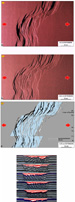
 Figure
7. Analog model E 354: Offset-Orthogonal Rift. (a) Overhead view of analog model
after 4 cm extension. (b) Overhead view of analog model after 7.5 cm extension
(50% stretching at the base of the model). Illumination is from the right. (c)
Line diagram interpretation of the surface fault pattern at the end of
extension. Dark bands are faults dipping to the left, and light bands are faults
dipping to the right. The blue shading marks the stretched rubber sheet at the
base of the model. (d) Serial sections through the offset-orthogonal rift model.
Synkinematic strata are the red and white layers at the top of the grabens on
each side of the central intrarift horst block. Location of sections is
indicated in (c). Figure
7. Analog model E 354: Offset-Orthogonal Rift. (a) Overhead view of analog model
after 4 cm extension. (b) Overhead view of analog model after 7.5 cm extension
(50% stretching at the base of the model). Illumination is from the right. (c)
Line diagram interpretation of the surface fault pattern at the end of
extension. Dark bands are faults dipping to the left, and light bands are faults
dipping to the right. The blue shading marks the stretched rubber sheet at the
base of the model. (d) Serial sections through the offset-orthogonal rift model.
Synkinematic strata are the red and white layers at the top of the grabens on
each side of the central intrarift horst block. Location of sections is
indicated in (c).
Click here for sequence
of Figure 7a, b, c.
Click here for sequence of sections shown in 7d.
 Figure
8. Analog model E 355: Offset 60 degrees Oblique Rift. (a) Overhead view of
analog model after 4 cm extension. Illumination is from the left. (b) Overhead
view of analog model after 8.65 cm extension (50% stretching at the base of the
model). Illumination is from the left.
(c) Line diagram interpretation of the surface fault pattern at the end of
extension. Dark bands are faults dipping to the right and light bands are faults
dipping to the left. The blue shading marks the stretched rubber sheet at the
base of the model. (d) Serial sections through the offset oblique rift model.
Synkinematic strata are the red and white layers at the top of the grabens on
each side of the central intrarift horst block. Location of sections is
indicated in (c). Figure
8. Analog model E 355: Offset 60 degrees Oblique Rift. (a) Overhead view of
analog model after 4 cm extension. Illumination is from the left. (b) Overhead
view of analog model after 8.65 cm extension (50% stretching at the base of the
model). Illumination is from the left.
(c) Line diagram interpretation of the surface fault pattern at the end of
extension. Dark bands are faults dipping to the right and light bands are faults
dipping to the left. The blue shading marks the stretched rubber sheet at the
base of the model. (d) Serial sections through the offset oblique rift model.
Synkinematic strata are the red and white layers at the top of the grabens on
each side of the central intrarift horst block. Location of sections is
indicated in (c).
Click here for sequence
of Figure 8a, b, c.
Click here for sequence of sections shown in 8d.
 Figure
9. Analog model E 356: Offset 45 degrees Oblique Rift. (a) Overhead view of
analog model after 4 cm extension. Illumination is from the left. (b) Overhead
view of analog model after 10.6 cm extension (50% stretching at the base of the
model). Illumination is from the left. (c) Line diagram interpretation of the
surface fault pattern at the end of extension. Dark bands are faults dipping to
the right, and light bands are faults dipping to the left. The blue shading
marks the stretched rubber sheet at the base of the model. (d) Serial sections
through the offset oblique rift model. Synkinematic strata are the red and white
layers at the top of the grabens on each side of the central intrarift horst
block. Location of sections is indicated in (c). Figure
9. Analog model E 356: Offset 45 degrees Oblique Rift. (a) Overhead view of
analog model after 4 cm extension. Illumination is from the left. (b) Overhead
view of analog model after 10.6 cm extension (50% stretching at the base of the
model). Illumination is from the left. (c) Line diagram interpretation of the
surface fault pattern at the end of extension. Dark bands are faults dipping to
the right, and light bands are faults dipping to the left. The blue shading
marks the stretched rubber sheet at the base of the model. (d) Serial sections
through the offset oblique rift model. Synkinematic strata are the red and white
layers at the top of the grabens on each side of the central intrarift horst
block. Location of sections is indicated in (c).
Click here for sequence
of Figure 9a b, c.
Click here for sequence of sections shown in 9d.
Return
to top.
Offset Rift Models
Offset rift models (Figures
7,
8,
9) were produced by making a preextension offset in the rubber sheet at the
base of the models (Figure
2c). These experiments produced strongly segmented rift models in which
offset depocenters were separated by complex accommodation zones of interlinked
faults without development of hard-linked strike-slip transfer faults (Figures
7,
8,
9).
In the
offset-orthogonal rift model, distinct offset graben systems developed at low to
moderate strains (Figure
7a). Both rift-border faults and intrarift faults were kinked with
soft-linked relay ramps, and they breached relays above the offsets in the basal
zone of stretching. Fault tips across these offset zones were strongly curved
and overlapped, producing synthetic, interlocking arrays (Figure
7b). After 50% extension, the border faults were strongly curved and linked
across the offsets, whereas the intrarift faults were more segmented (Figure
7b,
c). In serial sections, the rift was typically symmetrical, having two
grabens that developed adjacent to each border fault system; the graben axes
stepped across the offset zones in the basement (Figure
7d).
The 60 degrees and 45 degrees offset
rift models produced very similar rift structures (Figures
8,
9); both developed two different styles of accommodation zones above the
offsets in the zone of basement stretching. At low values of extension above the
left-stepping offset (lowermost offset in
Figures 8,
9), a relatively high-relief accommodation zone formed parallel to the
extension direction as a result of interlocking, oppositely dipping fault tips (Figures
8a,
9a). These interlocking faults display divergent fault-tip behavior (Figure
8b). In contrast, structurally low, oblique accommodation zones formed above
the right-stepping basement offsets (uppermost offsets in
Figures 8a,
9a). These were slightly oblique to the extension direction and consisted of
highly curved, interlocking extensional fault tips. At 50% extension at the base
of the model, the curved fault tips propagated along the accommodation zone and
formed interlocking oblique-slip fault arrays (Figures
8b,
9b). The 45 degrees offset model, in particular, developed small, elongate,
rhomboidal subbasins in these low-relief, oblique accommodation zones (Figure
9b).
These offset rift models generated
excellent examples of segmented dip domains, in which the dominant fault dip
changed across the accommodation zones (Figures
8c,
9c). This is reflected in the serial sections that show a dominant half-graben
asymmetry that flips polarity along strike across the offsets in the basal
stretching zone (Figures
8d,
9d). As in the other analog models (e.g.,
Figures 4,
5,
6), no discrete strike-slip transfer faults were developed.
Figure Captions (10-16)
 Figure
10. Accommodation zones formed in the model rifts. (a) Detail of an analog model
of a low-strain, relatively high-relief accommodation zone parallel/subparallel
to the extension direction. (b) Detail of an analog model of a high-strain,
relatively low-relief accommodation zone oblique to the extension direction.
Illumination is from the left. Figure
10. Accommodation zones formed in the model rifts. (a) Detail of an analog model
of a low-strain, relatively high-relief accommodation zone parallel/subparallel
to the extension direction. (b) Detail of an analog model of a high-strain,
relatively low-relief accommodation zone oblique to the extension direction.
Illumination is from the left.
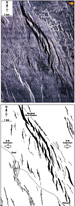
 Figure
11. East African rift system, Kenya. (a) Landsat thematic mapper (TM) image of
the Gregory rift west of Nairobi, Kenya. (b) Line diagram interpretation of (a)
showing the segmented and slightly offset rift-border fault system on the east
and a high density of north-south–oriented intrarift faults in the main part of
the rift. This pattern is characteristic of orthogonal rifting with the dominant
extension direction oriented east-west. Figure
11. East African rift system, Kenya. (a) Landsat thematic mapper (TM) image of
the Gregory rift west of Nairobi, Kenya. (b) Line diagram interpretation of (a)
showing the segmented and slightly offset rift-border fault system on the east
and a high density of north-south–oriented intrarift faults in the main part of
the rift. This pattern is characteristic of orthogonal rifting with the dominant
extension direction oriented east-west.
Click here for
sequence of Figure 11a, b.
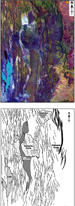
 Figure
12. (a) Radar image of the volcanic tablelands, Bishop, California. The image
shows a series of en echelon marginal faults in the Bishop tuff running
obliquely across the image with north-south-oriented interior faults in the
center left of the image. (Image courtesy of Conoco Exploration.) (b) Line
diagram interpretation of (a). This image is an example of oblique rifting with
the extension direction oriented east-west. Figure
12. (a) Radar image of the volcanic tablelands, Bishop, California. The image
shows a series of en echelon marginal faults in the Bishop tuff running
obliquely across the image with north-south-oriented interior faults in the
center left of the image. (Image courtesy of Conoco Exploration.) (b) Line
diagram interpretation of (a). This image is an example of oblique rifting with
the extension direction oriented east-west.
Click here for
sequence of Figure 12 a, b.
 Figure
13. (a) Oblique aerial photograph of offset grabens (1, 2, 3) in Canyonlands
National Park, Utah. At the terminations of individual grabens, the main faults
branch into a series of splays that form relay ramps between overlapping,
like-dipping faults and complex, conjugate arrays between oppositely dipping
faults. (b) Sketch map of the graben systems in Canyonlands National Park, Utah,
showing a series of offset graben systems formed by orthogonal extension and
linked by complex accommodation zones of interlocking faults. Figure
13. (a) Oblique aerial photograph of offset grabens (1, 2, 3) in Canyonlands
National Park, Utah. At the terminations of individual grabens, the main faults
branch into a series of splays that form relay ramps between overlapping,
like-dipping faults and complex, conjugate arrays between oppositely dipping
faults. (b) Sketch map of the graben systems in Canyonlands National Park, Utah,
showing a series of offset graben systems formed by orthogonal extension and
linked by complex accommodation zones of interlocking faults.
 Figure
14. Map of offset grabens and the oblique Redford Lajitas transfer zone,
southern Rio Grande rift, Texas (modi.ed from Henry, 1998). Extension direction
is averaged from data along the length of the extensional system. Figure
14. Map of offset grabens and the oblique Redford Lajitas transfer zone,
southern Rio Grande rift, Texas (modi.ed from Henry, 1998). Extension direction
is averaged from data along the length of the extensional system.
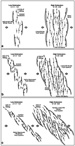 Figure
15. Conceptual extensional fault patterns for orthogonal and oblique rift
systems. These patterns are based partly on results of analog models described
in this article, as well as our studies of natural rift systems. (a) Orthogonal
rift fault systems. (b) Moderately oblique rift fault systems. (c) Strongly
oblique rift fault systems. Figure
15. Conceptual extensional fault patterns for orthogonal and oblique rift
systems. These patterns are based partly on results of analog models described
in this article, as well as our studies of natural rift systems. (a) Orthogonal
rift fault systems. (b) Moderately oblique rift fault systems. (c) Strongly
oblique rift fault systems.
 Figure
16. Accommodation zone models. (a) Conceptual 3-D model of a low-strain
accommodation zone parallel to the dominant extension direction. This zone is
formed by interlocking arrays of oppositely dipping faults and is typically
found above obtusely oriented basement transfer faults or in offset-orthogonal
rift systems (cf. Figures 7,
8, 10a).
(b) Conceptual 3-D model of an accommodation zone
oblique to the dominant extension direction. The zone is formed by interlocking
arrays of oppositely dipping faults and is typically found internally in the
analog models and has variable amounts of associated oblique shear (e.g.,
Figures 8, 9, 10b). Figure
16. Accommodation zone models. (a) Conceptual 3-D model of a low-strain
accommodation zone parallel to the dominant extension direction. This zone is
formed by interlocking arrays of oppositely dipping faults and is typically
found above obtusely oriented basement transfer faults or in offset-orthogonal
rift systems (cf. Figures 7,
8, 10a).
(b) Conceptual 3-D model of an accommodation zone
oblique to the dominant extension direction. The zone is formed by interlocking
arrays of oppositely dipping faults and is typically found internally in the
analog models and has variable amounts of associated oblique shear (e.g.,
Figures 8, 9, 10b).
Return to top.
Discussion
Analog Models
Analog models of
orthogonal and offset-orthogonal rift systems produce characteristically simple
rift systems that are approximately cylindrical along strike (Figures
4,
7). The rifts are defined by long rift-border faults that formed by
along-strike propagation of originally shorter, like-dipping segments that are
linked by breaching of classic, synthetic relay ramps (Larsen, 1988; Peacock and
Sanderson, 1991, 1994; Walsh and Watterson, 1991; Childs et al., 1995) (Figures
4,
7). The long, linked rift-border faults commonly display constant
displacement profiles along strike in the orthogonal rift model (Figure
4b). The intrarift zone of both these end members consists of two subbasins
oriented at right angles to the extension direction and separated by a linear (Figure
4) or offset (Figure
7) intrarift horst. The geometry of these orthogonal rift systems is set up
very early in the experiment; it extends from between the central part of the
rift and the rift margin and displays very little reorganization with increased
extension. In the offset-orthogonal rift system (Figure
7), the presence of a basal offset in the rift zone did not produce a
discrete transfer fault in the cover. Cover deformation around the offset zones
consisted of arcuate and linked rift-border faults and synthetic, interlocking
fault arrays that define the intrarift subbasins (Figure
7).
In contrast to orthogonal
rift systems, models run using oblique basement fabrics produce rift basins
having segmented rift-border faults that closely parallel the rift axis, and
intrarift fault domains that are oriented at a high angle to the extension
vector (Figures
5,
6). Oblique rift systems display significant structural variations along the
length of the rift zone, such as fault polarity switching that results in
generation of intrarift subbasins. In the model rifts, domains of different
fault polarities are separated by accommodation zones that are both parallel and
oblique to the regional extension direction (Figures
7,
8). Transfer of displacement between subbasins and regional highs in these
oblique models is effected by soft-linkage accommodation zones. In the 60
degrees oblique rift model (Figure
5), these accommodation zones consisted of interlocking fault arrays of
opposite dip polarities and divergent tips, which defined zones of relatively
high relief in the rift interior (Figures
5,
10a). Such interlocking extensional fault arrays also have been observed in
seismic data (Nichol et al., 1995) in which the conjugate fault zones were
regions of significant fault damage that were necessary to accommodate the
displacements on the oppositely dipping faults. These interlocking patterns were
established very early in the experiments and had a profound effect on the
evolution of the rift interior; they inhibited along-strike propagation of these
fault arrays and thereby strongly influenced observed fault length:displacement
ratios (Figure
5). In contrast, models run using 45 degrees rift obliquity initially
generated a similar pattern of interlocking opposite-polarity fault systems at
low strains, but with increasing displacement, these accommodation zones evolved
to oblique, low-relief accommodation zones (Figures
6,
10b). These accommodation structures were characterized by rotation of the
tips of opposite-polarity faults into subparallelism with the rift axis, forming
narrow, rhomboidal grabens subparallel to the axis of the rift (Figures
6,
10b).
Analog models of offset-oblique rifts
generated subbasins that displayed major dip polarity changes above the
hard-linked transfer zone in the basement (Figures
8,
9). In both of these offset rift systems (60 degrees and 45 degrees
oblique), two types of soft-linked accommodation zones were observed, dependent
upon the sense of basement offset with respect to the obliquity of the rift axis
(Figure
8,
9,
10). High-relief accommodation zones are subparallel to the extension vector
and are composed of interlocking opposite-polarity fault arrays characteristic
of deformation above left-stepping rift segmentation (Figure
8,
9,
10a). Low-relief accommodation zones were generated above right-stepping
rift segmentation. These zones consisted of opposite-polarity fault arrays that
show strong rotation into the accommodation zone and generated composite
accommodation zones oblique to the extension vector (Figure
8,
9,
10b). These accommodation zones are characterized by curvilinear grabens
that crosscut the basement offset and are bounded by the rotated tips of the
conjugate-fault sets (Figure
8,
9,
10b). The high degree of obliquity between the rotated tips of the
conjugate-fault sets and the extension vector necessitates a degree of oblique
slip along these zones.
Fault growth in the orthogonal and
offset-orthogonal rift models shows similar features to those that would be
expected if faults grew by a stress feedback mechanism (Cowie, 1998; Gupta et
al., 1998; Cowie et al., 2000). In Cowie's models, initially isolated, optimally
positioned faults rapidly link to form long, continuous, high-displacement fault
zones, or soft-linked, high-displacement, segmented rift-border faults (cf.
Cartwright et al., 1995). Orthogonal rift and offset-orthogonal rift models
display this characteristic growth model, having rift-border and intrarift fault
systems composed of long segments that are kinked where relay ramps have been
breached. In our models of oblique rifts, rift-border fault zones are not
continuous but consist of like-dipping fault segments linked by synthetic relay
ramps parallel to the rift axis. This segmentation increases as the obliquity of
the rift axis with respect to the stretching direction increases (e.g., 45
degrees rift in
Figure 6), such that high-angle, intrarift faults in these models take up
greater displacement than the border faults. These high-angle faults commonly
display tip-line rotation at the rift margin into parallelism with the basement
grain (e.g.,
Figure 5). Because of the position of these intrarift fault segments above a
uniformly stretching basement, instead of a linear velocity discontinuity at the
rift margin, they commonly form colinear arrays of opposite-polarity faults
whose along-strike propagation is hindered by their interlocking tip lines, thus
forming relatively high-relief accommodation zones (Figure
5,
6,
10). These interlocking accommodation features were formed early in the
evolution of the experiments and are long lived, preventing the linkage of
subbasins along the length of the rift.
Comparisons with Natural
Examples of Rift Systems
The scaled analog
models of rift fault systems described in this article show many similarities to
both outcrop and subsurface fault patterns of natural rifts. Whereas geometrical
similarities do not in themselves imply similar deformation mechanisms and
evolution pathways for the model geometries and the natural examples, strong
resemblances exist in their fault styles, patterns, and modes of propagation and
linkage to make reasonable comparisons between them.
Orthogonal Rifts
The Gregory rift in East
Africa shows excellent examples of segmented rift-border fault systems, as well
as long, relatively straight, intrarift faults in synrift Miocene volcanic units
(Figure
11). Both the rift-border and intrarift faults are dominantly north-south
striking and have long overlap regions between adjacent faults. Along-strike
displacement transfer is by soft-linked relay-ramp structures, and no
strike-slip or oblique-slip transfer faults are found (cf. Bosworth et al.,
1986). Extensional fault patterns having a similar lack of discrete, hard-linked
strike-slip transfer faults also have been observed in other parts of the East
African-Ethiopian rift system (cf. Ebinger, 1989a, b; Kronberg, 1991; Hayward
and Ebinger, 1996). Where originally segmented extensional faults have linked by
breaching of the relay ramps, distinct kinked-fault traces are developed (Figure
11a, b). This pattern is directly analogous to the model rift-fault patterns
developed in the orthogonal rift model (Figure
4) and indicate that the extension direction was dominantly east-west (cf.
Bosworth et al., 1986), orthogonal to the dominant intrarift and rift
marginal-fault systems. Patterns of initial-fault segmentation and subsequent
linkage similar to those in the analog models also have been found in
three-dimensional (3-D) seismic studies of Jurassic faults in the Viking Graben,
North Sea (McLeod et al., 2000).
Oblique and Offset Rifts
Oblique rifts are
characterized by en echelon rift marginal-fault systems oblique to the extension
direction and intrarift faults orthogonal to the extension direction (Figures
5,
6). Radar imagery from the extended volcanic tablelands in Owens Valley,
north of Bishop, California, shows the 700 ka Bishop tuff downthrown in a
north-northwest-trending extensional structure (Figure
12). The margins of this zone of extension are oblique to the
east-west-oriented extension (e.g., Dawers et al., 1993; Dawers and Anders,
1995) (Figure
12a). The marginal-fault systems are characterized by distinct relay-ramp
structures, whereas the internal faults, although sparsely developed, are at
high angles to the extension direction and are linked by breached relay ramps (Figure
12b). In a similar fashion to structures seen in the 60 degrees oblique-rift
model, parts of the marginal-fault system are composed of north-south, intrarift
segments that rotate along strike and link, to form the north-northwest-trending
margin (see
Figure 5,
12).
Two examples of offset
grabens and rift systems are shown in
Figures 13 and
14. In the Canyonlands example, the extension direction is orthogonal to the
series of discrete and linked grabens that form the rift system (Trudgill and
Cartwright, 1994) (Figure
13). An extension-parallel accommodation zone allows transfer of
displacement along strike between grabens 1 and 3 and is accommodated by
synthetic interlocking fault arrays defining graben 2 and separated by major
relay structures (Figure
13). In the southern Rio Grande rift, the Redford Lajitas transfer zone
accommodates displacement transfer between the northern subbasin (Redford Bolson)
and the southern subbasin (Big Bend National Park area) (Henry, 1998).
Fault-plane solutions and slickenside data indicate a dominant east-northeast
extension direction in this region, which is oblique to most of the mapped
surface faults (Henry, 1998) (Figure
14). Dextral oblique slip is recorded from faults in the Redford Lajitas
structure. The narrow Santana Bolson in this zone displays the lowest structural
relief in the region (Henry, 1998); it is similar to oblique accommodation
structures found above right steps in the 60 degrees and 45 degrees offset rift
models (Figures
8,
9,
10b,
14). The Redford Lajitas transfer/accommodation zone is situated above a
deeply buried east-west basement structure that is similar in orientation to the
basement offsets in the models. Further, to the north of the area illustrated in
Figure 15 is the Tascotal Mesa fault, a prominent east-west-trending
transfer fault that has demonstrable dextral slip along its length transferring
displacement eastward from the Redford Bolson to the Presidio Bolson (Henry,
1998). The difference in style between these two transfer or accommodation
structures is attributed to the shallow depth to basement below the Tascotal
Mesa structure (Henry, 1998). Basement control on the development of
accommodation zones in the Gulf of Suez rift is also described in Younes and
McClay (2002).
The comparative examples
of natural rift-fault patterns, together with the analog models described in
this article, have enabled the construction of several conceptual models for the
progressive evolution of rift-fault patterns in plan view (Figure
15). These diagrams illustrate the predicted initial fault patterns at low
values of extension (b = 1.1-1.3) and at
higher extensions (b > 1.5), where
originally segmented faults have linked along strike (Figure
15). Changes in subbasin (fault) polarities in these diagrams are indicated
by the development of accommodation zones formed by overlapping and interlocking
fault arrays. The 3-D synoptic models of the two dominant types of accommodation
zone, the high-relief extension-parallel accommodation zone (characteristic of
some orthogonal rift systems) and the low-relief oblique accommodation zone (as
observed in many of the models described in this article), are shown in
Figure 16.
Return to top.
Conclusions
Analog models of
oblique, stepped, and offset rifts characteristically produced rift-border fault
systems that linked by means of classic, synthetic relay ramps. In the model
rifts, however, domains of different fault polarities are separated by
accommodation zones that are both parallel (subparallel) and oblique to the
regional extension direction. In the extension-parallel accommodation zones, the
tips of oppositely dipping faults curve away from each other, forming an
anticlinal-like zone of high relief. Oblique accommodation zones evolve from
simple, interlocking arrays to form structural lows defined by oblique-slip
faults that parallel the rotated tips of the opposite-polarity fault sets. In
cross section, the accommodation zones consist of conjugate fault arrays formed
by the interlocking tips of oppositely dipping domino fault systems. In the
models, the accommodation zones form early in the evolution of the rift and
persist throughout the experiment history, thus influencing the ability of
faults to propagate along strike, prolong basin segmentation, and in some cases,
notably influence the fault length/displacement profiles.
The analog models and the natural
examples show that the architectures of rifts and, in particular, along-strike
switches in basin polarities and dominant fault dips across accommodation zones
are more complicated than previously published models of simple overlapping or
interlocking rift-border fault systems. The models developed two styles of
accommodation zones, both formed by interlocking, overlapping, intrarift fault
tips. High-relief accommodation zones are parallel or mildly oblique to the
extension direction, whereas low-relief accommodation zones are highly oblique
to the extension and are bounded by oblique-slip fault systems. No hard-linked,
extension-parallel, strike-slip or oblique-slip transfer faults were developed
in the models, in direct contrast to the extension-parallel, strike-slip or
oblique-slip transfer fault model commonly used to account for depocenter
changes and fault-polarity switches in rift systems.
REFERENCES CITED
Bally, A.W., 1981, Atlantic type margins, in Geology of
passive continental margins: history, structure and sedimentologic record: AAPG
Education Course Notes Series 19, p. 1-48.
Bosworth, W., 1985, Geometry of propagating continental rifts:
Nature, v. 316, p. 625-627.
Bosworth, W., 1994, A high-strain rift model for the southern
Gulf of Suez (Egypt), in J.J. Lambiase, ed., Hydrocarbon habitat in rift
basins: Geological Society Special Publication 80, p. 75-102.
Bosworth, W., P. Crevello, R.D. Winn Jr., and J. Steinmetz, 1986,
A new look at Gregory's rift: the structural style of continental rifting: EOS,
v. 67, p. 577, 582-583.
Cartwright, J.A., B.D. Trugdill, and C.S. Mansfield, 1995, Fault
growth by segment linkage: an explanation for scatter in maximum displacement
and trace length data from the Canyonlands grabens of SE Utah: Journal of
Structural Geology, v. 17, p. 1319-1326.
Childs, C., J. Watterson, and J.J. Walsh, 1995, Fault overlap
zones within developing normal fault systems: Journal of the Geological Society,
v. 152, p. 535-549.
Cloos, E., 1968, Experimental analysis of Gulf Coast fracture
patterns: AAPG Bulletin, v. 52, p. 420-444.
Cowie, P.A., 1998, A healing-reloading feedback control on the
growth rate of seismogenic faults: Journal of Structural Geology, v. 20, p.
1075-1087.
Cowie, P.A., S. Gupta, and N.H. Dawers, 2000, Implications of
fault array evolution for synrift depocentre development: insights from a
numerical fault growth model: Basin Research, v. 12, p. 241-261.
Dawers, N.H., and M.A. Anders, 1995, Displacement-length scaling
and fault linkages: Journal of Structural Geology, v. 17, p. 607-614.
Dawers, N.H., M.H. Anders, and C.H. Scholtz, 1993, Growth of
normal faults: displacement-length scaling: Geology, v. 21, p. 1107-1110.
Ebinger, C.J., 1989a, Geometric and kinematic development of
border faults and accommodation zones, Kivu-Rusizi rift, Africa: Tectonics, v.
8, p. 117-137.
Ebinger, C.J., 1989b, Tectonic development of the western branch
of the East African rift system: Geological Society of America Bulletin, v. 101,
p. 885-903.
Etheridge, M.A., J.C. Branson, and P.G. Stuart-Smith, 1987, The
Bass, Gippsland and Otway basins, southeast Australia: a branched rift system
formed by continental extension, in C. Beaumont and A.J. Tankard, eds.,
Sedimentary basins and basin-forming mechanisms: Canadian Society of Petroleum
Geologists Memoir 12, p. 147-162.
Faugere, E., and J.P. Brun, 1984, Modelisation experimentale de
la distention continentale: Compe Rendu Academie des Sciences Paris, v. 229,
ser. II, p. 365-370.
Faulds, J.E., and R.J. Varga, 1998, The role of accommodation
zones and transfer zones in the regional segmentation of extended terranes,
in J.E. Faulds and J.H. Stewart, eds., Accommodation zones and transfer
zones: the regional segmentation of the Basin and Range province: Geological
Society of America Special Paper 323, p. 1-46.
Gibbs, A.D., 1983, Balanced section constructions from seismic
sections in areas of extensional tectonics: Journal of Structural Geology, v. 5,
p. 153-160.
Gibbs, A.D., 1984, Structural evolution of extensional basin
margins: Journal of the Geological Society, v. 141, p. 609-620.
Gibbs, A.D., 1987, Development of extension and mixed-mode
sedimentary basins, in M.P. Coward, J.F. Dewey, and P.L. Hancock, eds.,
Continental extensional tectonics: Geological Society Special Publication 28, p.
19-33.
Gupta, S., P.A. Cowie, N.H. Dawers, and J.R. Underhill, 1998, A
mechanism to explain rift-basin subsidence and stratigraphic patterns through
fault array evolution: Geology, v. 26, p. 595-598.
Hayward, N., and C.J. Ebinger, 1996, Variations in the along-axis
segmentation of the Afar rift system: Tectonics, v. 15, p. 244-257.
Henry, C.D., 1998, Basement-controlled transfer zones in an area
of low-magnitude extension, eastern Basin and Range province, Trans-Pecos Texas
in J.E. Faulds and J.J. Stewart, eds., Accommodation zones and transfer
zones: the regional segmentation of the Basin and Range province: Geological
Society of America Special Paper 323, p. 75-89.
Horsfield, W.T., 1977, An experimental approach to
basement-controlled faulting: Geologie en Mijnbouw, v. 56, p. 363-370.
Horsfield, W.T., 1980, Contemporaneous movement along crossing
conjugate normal faults: Journal of Structural Geology, v. 2, p. 305-310.
Karner, G.D., and N.W. Driscoll, 1999, Tectonic and stratigraphic
development of the west African and eastern Brazilian margins: insights from
quantitative basin modelling, in N.R. Cameron, R.H. Bate, and V.S. Clure,
eds., The oil and gas habitats of the South Atlantic: Geological Society Special
Publication 153, p 11-40.
Kronberg, P., 1991, Geometries of extensional fault systems,
observed and mapped on aerial and satellite photographs of Central Afar
(Ethiopia/Djibouti): Geologie en Mijnbouw, v. 70, p. 145-161.
Larsen, P., 1988, Relay structures in a Lower Permian
basement-involved extension system, East Greenland: Journal of Structural
Geology, v. 10, p. 3-8.
Lister, G.S., M.A. Etheridge, and P.A. Symonds, 1986, Detachment
faulting and the evolution of passive continental margins: Geology, v. 14, p.
246-250.
McClay, K.R., 1990a, Extensional fault systems in sedimentary
basins: a review of analogue model studies: Marine and Petroleum Geology, v. 7,
p. 206-233.
McClay, K.R., 1990b, Deformation mechanics in analogue models of
extensional fault systems, in R.J. Knipe and E.H. Rutter, eds.,
Deformation mechanisms, rheology and tectonics: Geological Society Special
Publication 54, p. 445-453.
McClay, K.R., and M. White, 1995, Analogue models of orthogonal
and oblique rifting: Marine and Petroleum Geology, v. 12, p. 137-151.
McLeod, A., N.H. Dawers, and J.R. Underhill, 2000, The
propagation and linkage of normal faults: insights from the
Strathspey-Brent-Stratfjord fault array, northern North Sea: Basin Research, v.
12, p. 263-284.
Morley, C.K., 1994, Structural geology of rifts, in J.J.
Lambiase, ed., Hydrocarbon habitat in rift basins: Geological Society Special
Publication 80, p. 75-102.
Morley, C.K., R.A. Nelson, T.L. Patton, and S.G. Munn, 1990,
Transfer zones in the East African rift system and their relevance to
hydrocarbon exploration in rifts: AAPG Bulletin, v. 74, p. 1234-1253.
Moustafa, A.R., 1997, Controls on the development and evolution
of transfer zones: the influence of basement structure and sedimentary thickness
in the Suez rift and Red Sea: Journal of Structural Geology, v. 19, p. 755-768.
Nelson, R.A., T.L. Patton, and C.K. Morley, 1992, Rift-segment
interaction and its relation to hydrocarbon exploration in continental rift
systems: AAPG Bulletin, v. 76, p. 1153-1169.
Nichol, A., J.J. Walsh, J. Watterson, and P.G. Bretan, 1995,
Three-dimensional geometry and growth of conjugate normal faults: Journal of
Structural Geology, v. 17, p. 842-862.
Patton, T.L., A.R. Moustafa, R.A. Nelson, and S.A. Abdine, 1994,
Tectonic evolution and structural setting of the Suez rift, in S.M.
Landon, ed., Interior rift basins: AAPG Memoir 59, p. 9-56.
Peacock, D.C.P., and D.J. Sanderson, 1991, Displacement and
segment linkage and relay ramps in normal fault zones: Journal of Structural
Geology, v. 13, p. 721-733.
Peacock, D.C.P., and D.J. Sanderson, 1994, Displacements, segment
linkage and relay ramps in normal fault zones: AAPG Bulletin, v. 78, p. 147-165.
Rosendahl, B.R., 1987, Architecture of continental rifts with
special reference to East Africa: Annual Review of Earth and Planetary Sciences,
v. 15, p. 445-503.
Rosendahl, B.R., D. Reynolds, P. Lorber, C. Burgess, J. McGill,
D. Scott, J. Lambiase, and S. Derksen, 1986, Structural expressions of rifting:
lessons from Lake Tanganyika, in L.E. Frostick et al., eds.,
Sedimentation in the East African rifts: Geological Society Special Publication
25, p. 29-43.
Serra, S., and R.A. Nelson, 1989, Clay modelling of rift
asymmetry and associated structures: Tectonophysics, v. 153, p. 307-312.
Tron, V., and J.-P. Brun, 1991, Experiments on oblique rifting in
brittle-ductile systems: Tectonophysics, v. 188, p. 71-84.
Trudgill, B., and J. Cartwright, 1994, Relay-ramp forms and
normal-fault linkages, Canyonlands National Park, Utah: Geological Society of
America Bulletin, v. 106, p. 1143-1157.
Walsh, J.J., and J. Watterson, 1991, Geometric and kinematic
coherence and scale effects in normal fault systems, in A.M. Roberts, G.
Yielding, and B. Freeman, eds., The geometry of normal faults: Geological
Society Special Publication 56, p. 193-203.
Withjack, M.O., and W.R. Jamison, 1986, Deformation produced by
oblique rifting: Tectonophysics, v. 126, p. 99-124.
Younes, A.I., and K.McClay, 2002, Development of accommodation
zones in the Gulf of Suez-Red Sea rift, Egypt: AAPG Bulletin, v. 86, no. 6, p.
1003-1026.
Return to top.
AUTHORS
Ken McClay graduated with
a B.Sc. (honors) degree from Adelaide University, Australia. He subsequently
undertook an M.Sc. degree in structural geology and rock mechanics at Imperial
College, London University, where in 1978 he also obtained a Ph.D. in structural
geology. He was awarded a D.Sc. by Adelaide University, Australia, in 2000. He
is BP Professor of Structural Geology and director of the Fault Dynamics
Research Group at Royal Holloway University of London. His research involves the
study of extensional, thrust, strike-slip, and inversion terranes and their
applications to hydrocarbon exploration. He publishes widely, consults, and
offers short courses to industry.
Tim Dooley, a native of
Waterford, Ireland, graduated with a B.A. (honors) degree (Mod.) from Trinity
College Dublin, Ireland, in 1988. Subsequently, he undertook a Ph.D. in
structural geology at Royal Holloway University of London. Since 1994 Tim has
been a postdoctoral research assistant with the Fault Dynamics Research Group in
the structural modeling laboratories at Royal Holloway. His current research
interests include analog modeling of extensional, strike-slip, salt and shale,
and compressional tectonics, as well as developing graphic and interactive
techniques for the presentation of these data to students and industry.
Paul Whitehouse graduated
from the University of Birmingham in 1996 with a B.Sc. degree in geology. In
1998, he completed an M.Sc. degree in basin evolution and dynamics at Royal
Holloway University of London before joining the Fault Dynamics Research Group
as a postgraduate research assistant. His recent research topics include analog
modeling of three-dimensional extensional fault systems and analog modeling of
doubly vergent thrust wedges. His current work concentrates on fault and
fracture systems in extensional tectonic settings, incorporating analog modeling
and field studies in the Gulf of Suez, Egypt. modeling
and field studies in the Gulf of Suez, Egypt.
Michelle Mills graduated
from the University of Edinburgh in 1997 with a B.Sc. degree in geology, having
spent her third year at the University of California, Santa Cruz. She spent a
year as a voluntary worker before completing her M.Sc. degree in tectonics at
Royal Holloway College in 1999. She currently works at Heriot-Watt University
evaluating computer-aided learning software for engineering.
ACKNOWLEDGMENTS
This research was
supported by the Natural Environment Research Council (NERC) ROPA Grant
GR3/R9529. Additional support came from the Fault Dynamics Project (sponsored by
ARCO British Limited, Petrobras U.K. Ltd., BP Exploration, Conoco [United
Kingdom] Limited, Mobil North Sea Limited, and Sun Oil Britain). McClay also
gratefully acknowledges support from BP Exploration. Howard Moore and Mike
Creager constructed the deformation apparatus. This article is Fault Dynamics
Publication 101.
Return to top.
|