Classifications of Syndepositional Systems and Tectonic Provinces of the Northern Gulf of Mexico
JOHN F. KARLO, Shell Exploration and Production Technology Co., Houston TX and ROBERT C. SHOUP, Samson Offshore, Houston TX, formerly of Shell Deepwater Development Inc., New Orleans La.
Search and Discovery Article #30004 (2000)
Adaptation for online presentation from poster session at Houston Geological Society Dinner Meeting, February 7, 2000; it is presented here with the kind permission of Shell Oil Company.
Editorial Note: This article, which is highly graphic (or visual) in design, is presented as: (1) three posters, with (a) each represented by a small, low-resolution image map of the original; each illustration or section of text on each poster is accessible for viewing at screen scale (higher resolution) by locating the cursor over the part of interest before clicking; and (b) each represented by a pdf image, which contains the usual enlargement capabilities; and (2) HTML text and abbreviated figure captions linked to corresponding illustrations with descriptions.
Users without high-speed internet access to this article may experience significant delay in downloading many of these illustrations due to their sizes.
First Poster -Summary, Structural Systems Concept, Shale-based and Salt-based Detachments, Salt Withdrawal Mini-basins
![]() Click here to view pdf version of the First Poster.
Click here to view pdf version of the First Poster.
Second Poster -Regional Tectonics
![]() Click here to view pdf version of the Second Poster.
Click here to view pdf version of the Second Poster.
Third Poster -Salt Withdrawal Mini-basins
![]() Click here to view pdf version of the Third Poster.
Click here to view pdf version of the Third Poster.
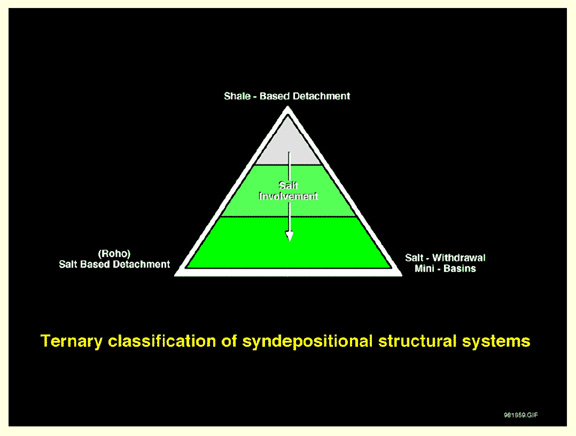
In the northern Gulf of Mexico Basin there are three end member types of structural complexes that are the genetic units for load induced growth faulting: shale-based detachment faults, salt-withdrawal mini-basins, and salt-based detachment faults.
These complexes, or Structural Systems, are on the same tens of kilometers scale as the deltaic and turbidite depositional systems that are the driving loads.
Because the individual components that make up a structural system, including the reservoir, are genetically related, they tend to occur within the system in an orderly and generally repetitive pattern.
With a good understanding of the general patterns of syndepositional systems, one has a predictive tool to apply to the specifics of an area or prospect being evaluated.
These systems are not distributed at random but are segregated into areas, or Tectonic Provinces, dominated by one type of system.
The provinces have an organized, successional pattern, reflecting some of the fundamental controls on the development of the basin.
The largest scale control on the tectonics of the northern Gulf Basin was the initial division of the basin into a western, high standing rift platform with a thin veneer of salt juxtaposed against a plunging-ramp rift profile with a basinward thickening wedge of salt to the east.
Structural Systems Concept
Syndepositional structural systems are:
-
Large - scale structural complexes formed in response to syndepositional loading of an unstable substrate
-
Comprised of a number of different, yet genetically related components which occur in an orderly repetitive pattern within the system
The occurrence and location of all the components of a syndepositional structural system are generally predictable, including the reservoirs!
Ternary classification of syndepositional structural systems
System Models
Shale-based Detachment Systems
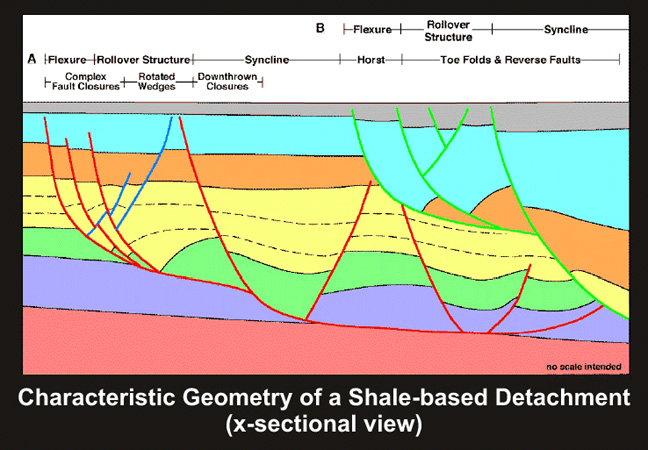
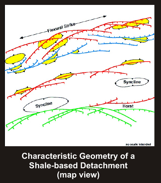
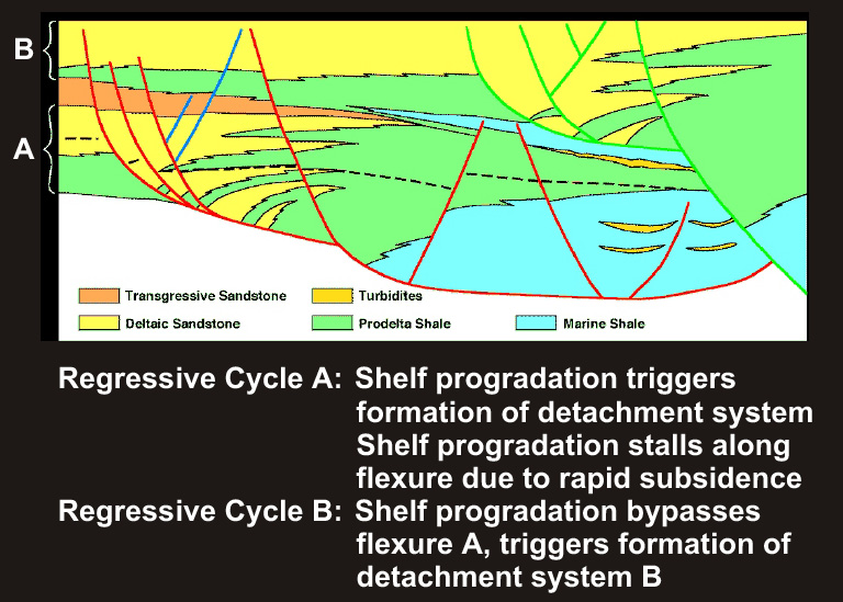
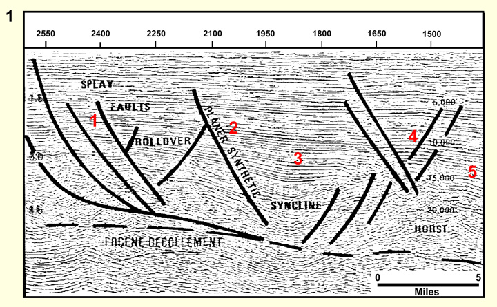
Shale-Based Detachment Systems are gravity slide phenomena driven by progradation of the shelf margin onto an unstable shale resulting in a regional decollement. The updip zone of extension is characterized by listric splay and keystone faults and by the development of rollover structures and/or rotated fault blocks. Delta progradation stalls at the head of the system and sands tend to be stacked in the rollover, or are conveyed downdip along the fault ramp to form rotated wedges. In map view, the linear region of splay and keystone fault development is the zone which historically has been called the 'flexure'. The basinward edge of the flexure is a planar synthetic fault beyond which is a synclinal region. Tectonically this is the true first order structure of the gravity slide, and is typically filled with prodelta slope facies. Further basinward is the relatively undeformed slide block, typically seen as a horst, generally starved of coeval sedimentation and terminating in a compressional toe zone. The slide block and toe zone are often obscured or removed by the next younger system.
First order components of a shale-based detachment system
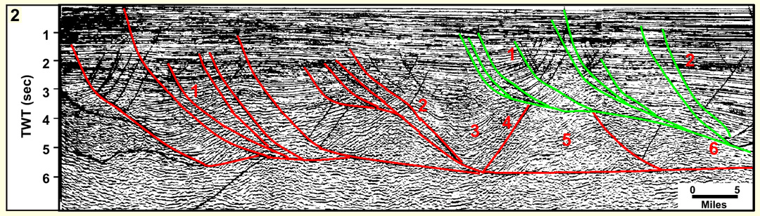
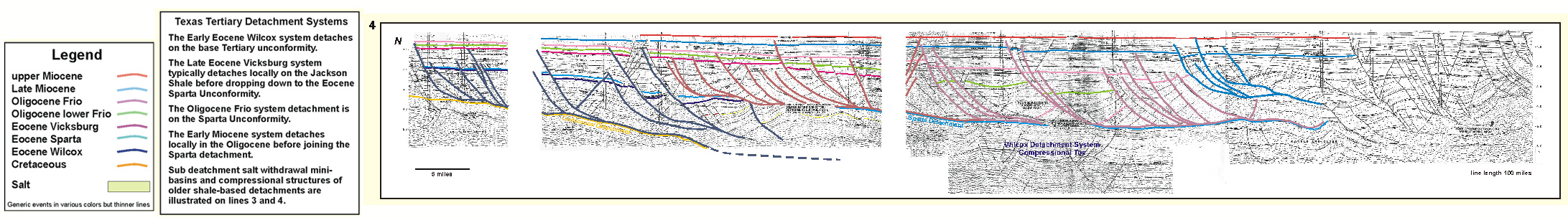
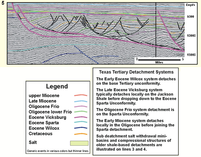
Texas Tertiary detachment systems
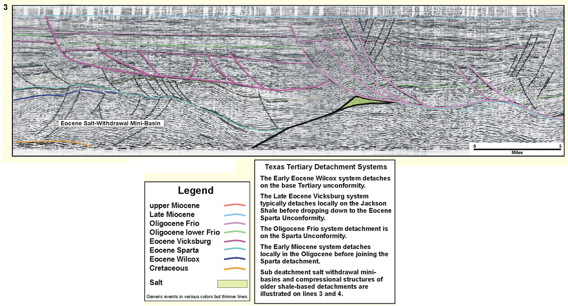
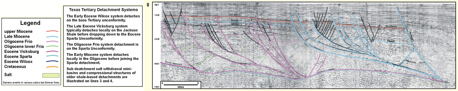
Texas Miocene Compressional Belt
A poorly described belt of tight folds and reverse faults bounds the Detachment Province, extending from Port Isabel OCS through High Island OCS with some discontinuous local areas of similar structure seen as far east as East Cameron OCS. Although it is obvious that these structures are the companion toe folds of the up dip Miocene growth faults, the structural history and the amount of shortening taken up by the structures is not determined.
The detachment province consists regionally of stacked detachments at different stratigraphic levels. Where the data allows resolution beneath one detachment to a deeper detachment level we see evidence of older fold belts as companions to the older growth fault systems (for example see composite seismic profile in Detachment Province in East Texas). The older and deeper belts are at this time barely recognized and have no well control.
Salt-based Detachment Systems
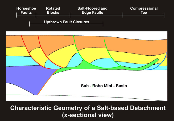
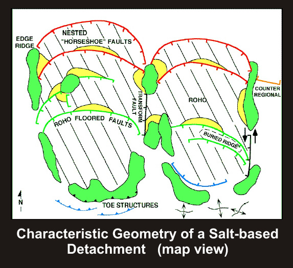
Salt-Based Detachment systems (Roho*) are combination gravity slides and salt withdrawal structures formed in response to the progradation of shelf sediments onto a salt wing. The updip zone of extension is marked by a series of nested highly listric faults, which in map view, display a characteristic horseshoe geometry. Deltaic sands and shales tend to be stacked in the rotated wedges associated with these faults. The central portion of the structural system is typically manifest as a complicated zone of remnant salt, perched diapirs, salt-floored faults, and strike slip faults. Basinward of this region is the compressional toe, which consists of a melange of salt and deformed sediment. All faults sole into the evacuated remnant of the original salt tablet, which typically overlies a salt-withdrawal mini-basin. In map view, the overall geometry of the salt-based detachment system is constrained by the geometry of the salt tablet upon which it is forming.
First Order components of a salt-based Roho* detachment system
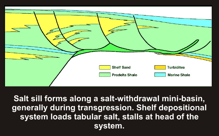
Formation of salt sill along salt-withdrawal mini-basin
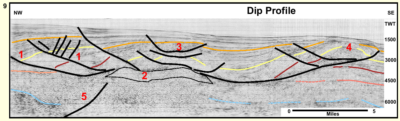
Seismic sections of salt-based detachment systems from Offshore Louisiana
Type (seismic) section 9 (dip )
Type (seismic) section 10 (strike)
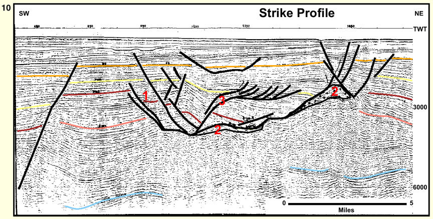
The detachment surface for these growth-faults is evacuated salt. On 1960's and 1970's vintage seismic data, it was not possible to image below the salt evacuation surface. An early Shell worker, Chuck Roripaugh, after being instructed to map to the Moho, jokingly labeled his map of the salt evacuation as "Roripaugh's Moho" which was later contracted to ROHO. This in-house joke has since escaped into the public literature.
Salt Withdrawal Mini-basins
These are characterized as (1) shelf-loaded and (2) slope-loaded, which are described under the main heading, "Salt Withdrawal Mini-basins."
Shelf-loaded mini-basins
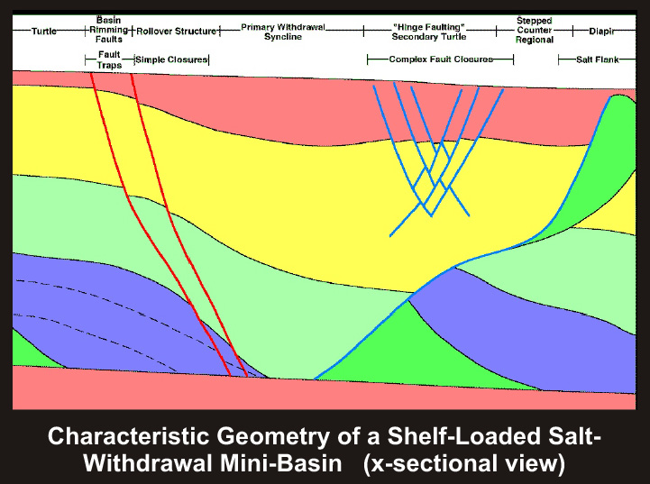
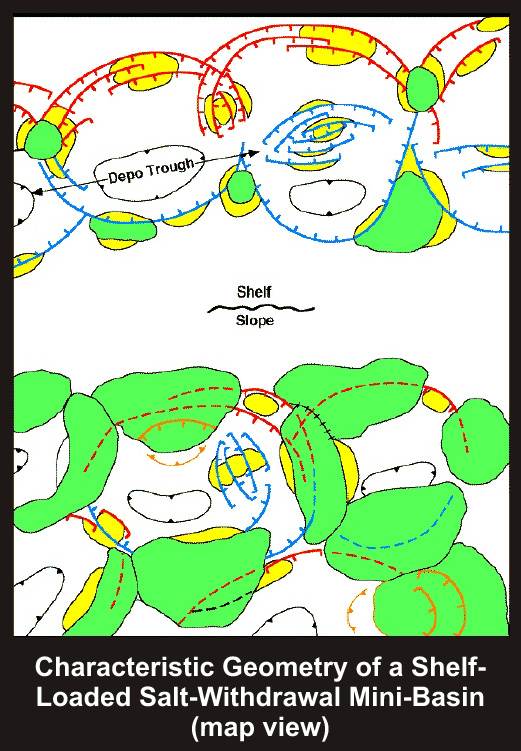
Characteristic geometry of shelf-loaded mini-basins
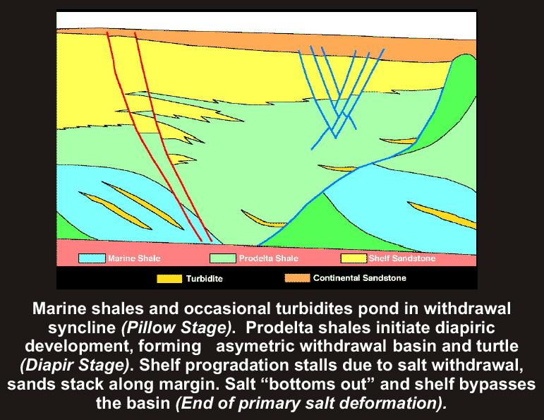
Primary salt deformation and withdrawal basin (cross-sectional view)
Slope-loaded mini-basins
Characteristic geometry of slope-loaded mini-basins
Primary salt deformation and withdrawal basin (cross-sectional view)
Regional Tectonics
Description of the Principal Structural Provinces
Buried Peripheral Salt Features
-
Mesozoic and Early Tertiary structures.
-
Updip belt of low amplitude salt pillows and rollers, minor salt withdrawal synclines and rafted blocks.
-
Downdip belt of low amplitude salt withdrawal mini-basins and small diapirs, typically stationary at top chalk, buried beneath Upper Tertiary shelf sediments and structures.
-
Multiple detachment surfaces, which may be local or regional step up section basinward. Detachment levels recognized locally at top Cretaceous, top chalk, Top Wilcox Unconformity, Jackson Shale, Anahuac Shale and Amp. Shale.
-
Associated with downdip belt of complex chevron folding and reverse faulting.
-
Stratigraphically higher detachments (perched detachments) may drop to a lower level forming a prominent knee in the overall sole of the fault system.
-
Rotation of fault surfaces via underlying subsidence often creates local areas with flat lying fault planes (pseudo detachment geometries).
-
Superimposed over Buried Peripheral Salt Features which show as salt diapirs and wings, mini-basins and counter regional faults below detachment, commonly at top chalk.
-
Scattered late reactivation of salt movement induces sags in detachments while they are active and piercing of detachments by diapirs rooted in autochthonous salt.
-
Salt withdrawal mini-basins rooted into autochthonous salt at 40-45,000 ft. with subsidence histories continuous at least from the Cretaceous.
-
Basins aligned in sub parallel linear trends with salt domes intermittently along the bounding faults.
-
Characterized updip by simple mini-basins and downdip by stepped counter regional fault basins.
-
Stepped counter regional basins show a secondary turtle structure on the 'step' and some local ROHO development.
-
Associated salt masses grade from simple diapirs updip into larger volume, overhung salt domes and successively into salt wings downdip.
-
Remnant salt evacuation surfaces and secondary salt diapirs derived by remobilization of allochthonous salt tablets that rooted back into autochthonous salt.
-
Pre evacuation tablets emplaced in paleo slope, subsequently loaded by shelf sediments. Present evacuation surface generally separates hydropressure shelf from geopressure slope regimes.
-
Amalgamated salt tablets, original tablets outlined by lateral evacuation of salt into edge ridges.
-
ROHO serves as detachment surface for down to basin growth faults with some down dip toe thrusting.
-
Areas of ROHO may be continuous with regular overlying structure (organized ROHO) or patchy with variable overlying structural styles (disorganized ROHO), linked to the original degree of tablet amalgamation.
-
Seismic resolution poor but some underlying salt withdrawal minibasin/counter regional fault geometries are discernable.
Primary Minibasin -Tabular Salt Province
-
Thick tablets of salt, rooted into autochthonous salt, amalgamated over large area (salt canopy) but preserving some windows into the deeper section.
-
In the west Tabular salt is continuous with the ROHO province that derived from such tablets but eastward and westward it is associated with primary salt withdrawal mini-basins that fed the tablets.
-
Mini-basins generally simple, flanked by salt walls with little fault rim development. These mini-basins are both at an earlier stage of development and they involve more salt than the more structurally complex shelf mini-basins. Plio-Pleistocene mini-basins 'bottom out' into turtle structures of at least Cretaceous age.
-
Individual tabular salt masses clearly recognizable to east and west but boundaries become harder to recognize with increasing coalescence of tablets toward basin center. Salt masses average 5-10,000' in east Louisiana and Texas slopes, thicken to 10-20,000' in central Louisiana.
-
Tablet boundaries not defined within the Salt Canopy but coalesced nature discernible from multiple examples of south tapering salt wedges, shingled salt overlying salt with encased sediments caught between and sub regionally traceable flow fronts .
-
Salt and thrust cored folds ( Perdido and Mississippi Fan belts) that protrude from beneath the shallower overthrusting salt canopy.
-
Faults sole into and folds are cored by autochthonous salt.
-
Fold belts are limited downdip by depositional/tectonic limit of salt at edge of oceanic crust.
-
Linkage between fold belts and age equivalent structures updip, generally Oligocene in the Perdido and Miocene in the Mississippi Fan belt is currently only speculative.
Map of Gulf of Mexico principal structural provinces
The salt features and associated withdrawal basins make up an ordered but gradational sequence of structural styles across the shelf and slope. The sequence (above) progresses from updip basins with static diapirs that aborted and were buried, to the most downdip withdrawal basins that have been active since the Mesozoic and are related to an amalgamated and fully allocthonous salt canopy.
This progressive change in the volume of salt displacement and also the continuity in salt movement is interpreted as the direct result of an original increasing salt supply downdip from a basinward thickening depositional salt wedge.
The deep water salt canopy has been taken as a uniformitarianistic element in a number of interpretations of the tectonic history of the Gulf of Mexico. It has been interpreted as the latest in a series of multiple canopies that step basinward through time. In those models the mini-basins of the shelf and upper slope root into these older canopies.
The deep record length seismic currently available to industry now makes such an interpretation untenable. The shelf mini-basins, Roho salt-feeder systems and primary mini-basins of the slope bottom out into complex collapse structures floored by a continuous set of reflectors at approximately 9-9.5 sec (40-45,000') that are correlated with the autochthonous Luann salt level.
The eastern half of the basin has a full progression of salt related structural styles, while the western half of the basin has a wide area lacking major salt structures that abruptly juxtaposes against tabular salt. This differentiation is interpreted as resulting from a fundamental division between a gradually thickening wedge in the eastern half of the basin and a thin salt veneer that abruptly thickened in the western half.
The gravity slide detachments characteristic of the western half of the basin are superimposed over salt related structures where original salt thickness was insufficient to maintain structural growth. The shale based systems terminate both downdip and to the east where original salt thickness was sufficient to maintain long term structural growth.
Irregularities in salt deformation style within a province, such as occurrence of a patch of Roho in a non-Roho area, are indicative of local variations in original salt thickness.
Types of structure in relation to increasing salt thickness
The areal distribution of the provinces is related to differing original salt thicknesses where the depositional thickness depended on the basement structure of different crustal types from rifting, crustal fragmentation along transform faults and the structural style of the rift margin profile.
The very thick salt under the present day slope formed in the main sag basin over attenuated crust along the zone of continental rifting. The updip limit of the main basin is controlled by a basement hinge at the limit of strongly attenuated crust. The downdip limit of the salt basin occurs at approximately the boundary with oceanic crust.
The onshore salt basins and the Desoto Salt Basin were deposited in subsidiary grabens in normal crust that flank or branch off the main rift basin. Between these subsidiary grabens only a relatively thin veneer of evaporites was deposited.
The fundamental difference between the Texas and Louisiana halves of the basin is interpreted as derived from having a platform profile to the west with an abrupt transition into a narrow zone of crustal stretching, and a ramp profile to the east with a comparatively broad zone of stretching. These are separated by a significant transform boundary located coincidentally near the offshore extension of the Texas Louisiana State line. This difference in the structural style of the rift margin created a wide zone devoid of significant salt features across coastal Texas and corresponding shelf contrasting with a wide overall salt basin extending far up dip across the Louisiana shelf.
Gulf of Mexico diagrammatic original salt distribution
Map of free area gravity: low frequency component
Map of total field magnetics, DNAG, reduction to pole (shaded relief)
General Statement
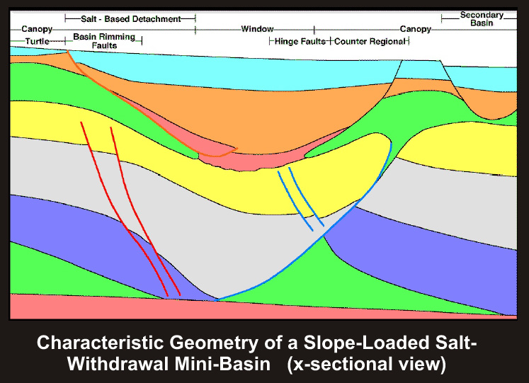
Salt-Withdrawal Mini-basin Systems are circular to elliptical in map view. They are comprised of an asymmetric salt-withdrawal syncline with its coupled diapir(s), a north dipping 'counter regional' fault and secondary basin rimming hinge faults. When the counter-regional is stepped, there will also be a secondary turtle and/or a series of hinge faults. The overall geometry of the mini-basin, and the nature of the sedimentary fill within the basin vary considerably depending on whether the mini-basin was loaded primarily in a shelf or slope environment.
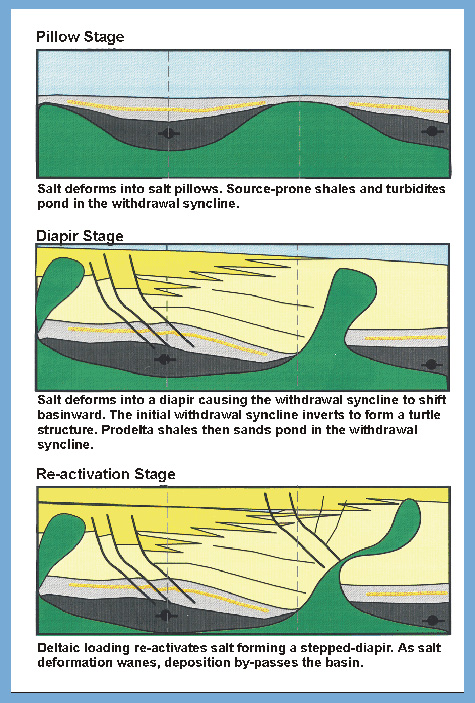
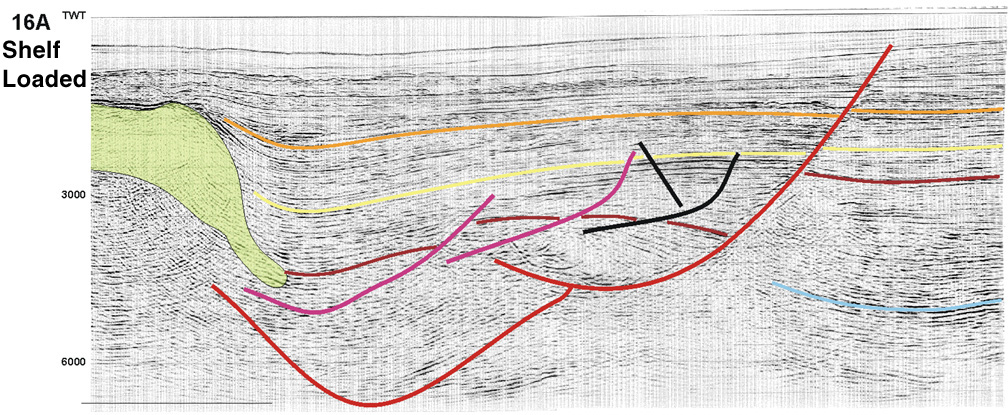
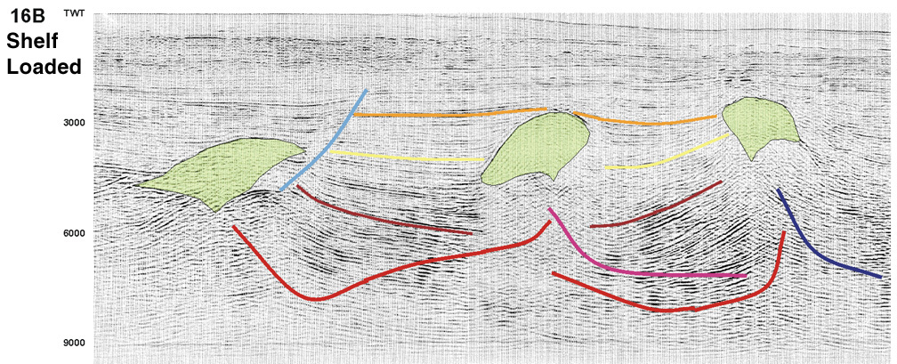
Shelf-loaded mini-basins are formed, see cartoon, by loading of allochthonous salt. After an initial salt pillow stage, driven by deep water sedimentation, shelf sedimentation caused rapid withdrawal of salt from the basin into diapirs. An asymmetric wedge of prodeltaic shale filled the developing syncline. The shelf margin stalled along the basin-rimming hinge faults resulting in a thick section of stacked deltaic sands and shales. In map view, shelf-loaded salt withdrawal mini-basins are typically aligned, forming a depo-trough.
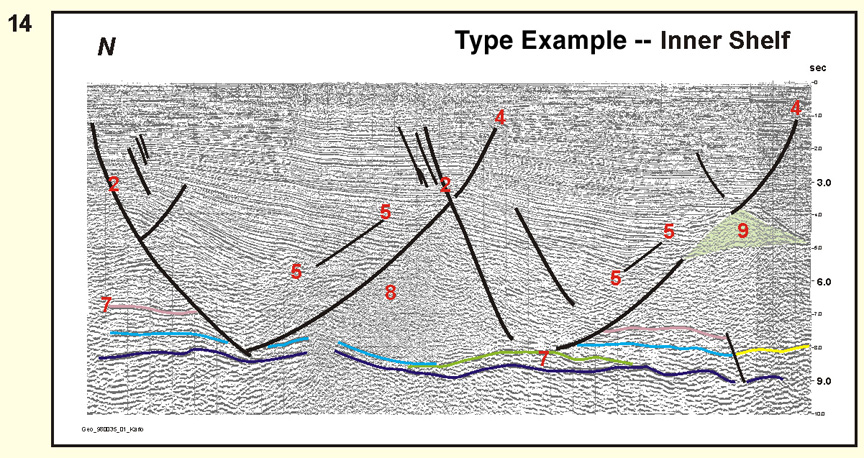
Inner shelf type (seismic) section 14
Shelf-Loaded
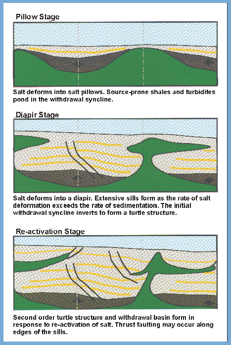
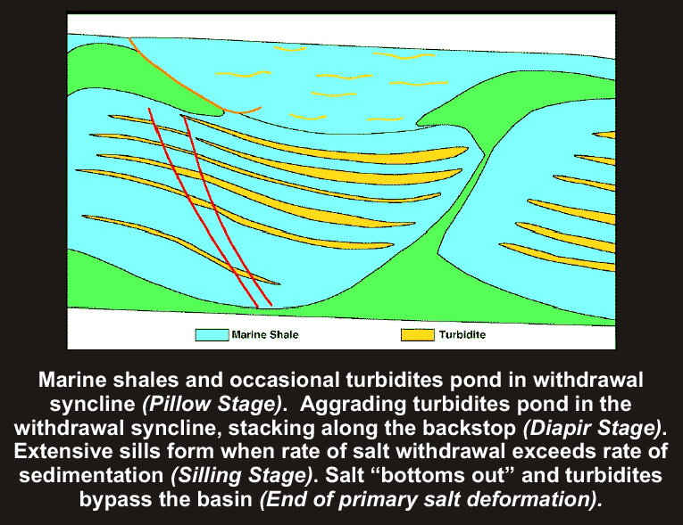
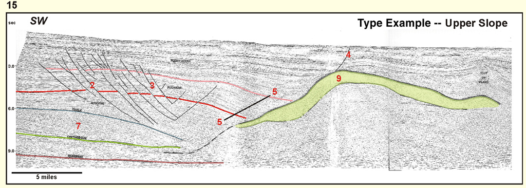
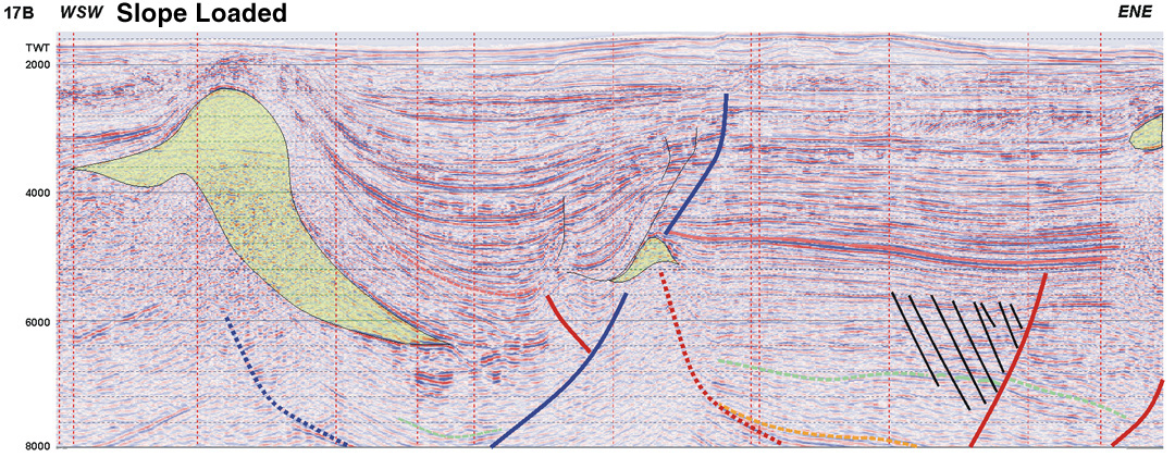
Slope-loaded mini-basins are similar to shelf mini-basins, but involve much more salt than the shelf systems, see cartoon. The slope withdrawal basins are flanked by salt walls with little fault rim development. Formation of the slope-loaded mini-basins began with ponding of turbidites triggering the diapiric stage. Because of the great thickness of autochthonous salt involved, turbidite ponding is more or less continuous, so long as there is salt withdrawing from the basin. Should the depocenter shift during the diapiric phase, a wing forms during the hiatus which overflows the basin resulting in the formation of a salt canopy. Once the allochthonous salt has been evacuated, subsequent turbidite deposition bypasses the basin.
Development of withdrawal syncline (basin) in cross-sectional views
Upper slope - Type (seismic) section 15
Other seismic sections of slope-loaded mini-basins
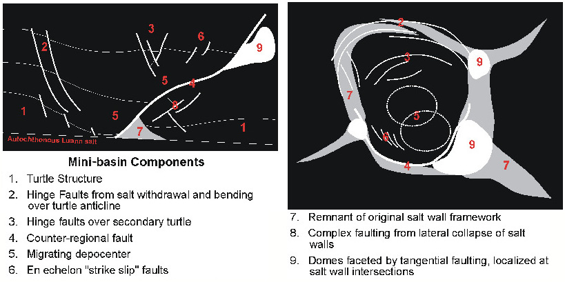
Mini-basin Components
-
Turtle Structure
-
Hinge Faults from salt withdrawal and bending over turtle anticline
-
Hinge faults over secondary turtle
-
Counter-regional fault
-
Migrating depocenter
-
En echelon "strike slip" faults
-
Remnant of original salt wall framework
-
Complex faulting from lateral collapse of salt walls
-
Domes faceted by tangential faulting, localized at salt wall intersections
Mini-basin components (cross-sectional and map views)
Structural Strike and Dip in Semi-circular to Elliptical Basins
For semi-circular to elliptical mini-basins, structural strike and dip take on a somewhat different meaning.
For individual mini-basins, lines acquired through a mini-basin's center are considered dip cuts (lines 14, 15). Lines acquired along a mini-basin's margin, or edges, are considered strike cuts (lines 16, 17A). On strike cuts, faults characteristically display a U-shape.
Details and Variations
Seismic section 18--around updip edge of basin are small mini-basins with static salt
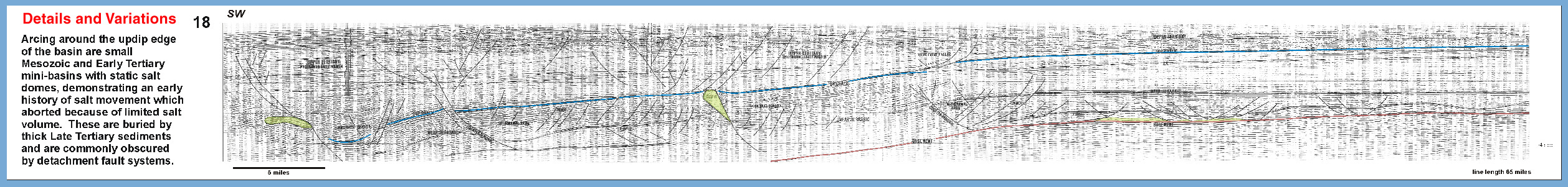
Seismic section 19--increasing complexity in mini-basin development downdip
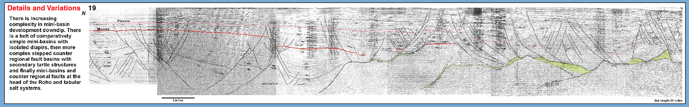
Seismic section 20--salt withdraws from slope-loaded mini-basins
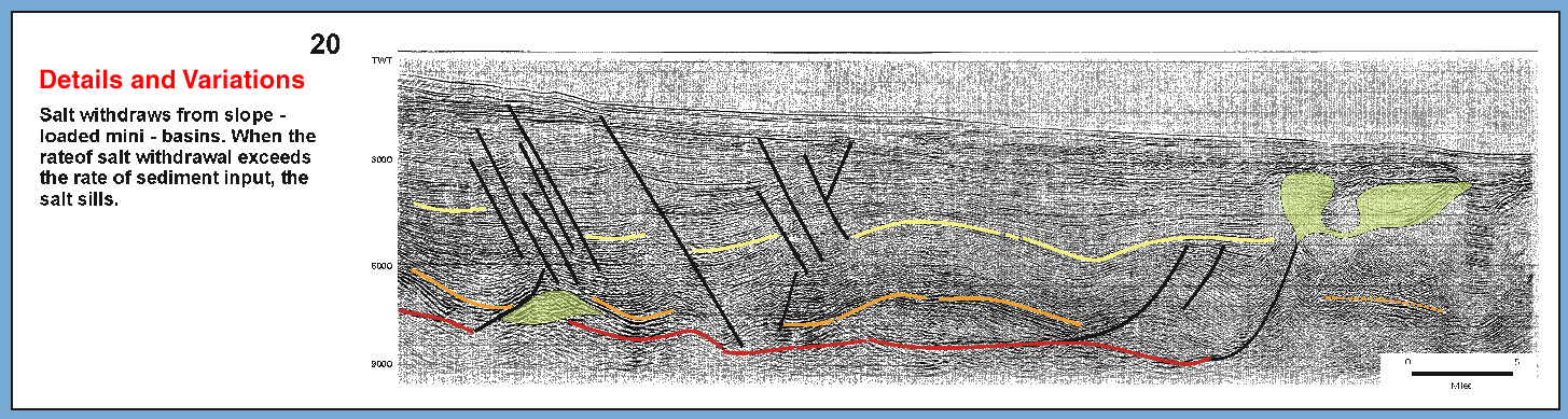
Seismic section 21--sills can flow updip and downdip
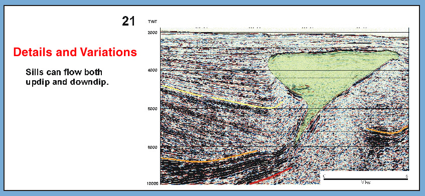
Seismic section 22--sills coalescing to form canopy
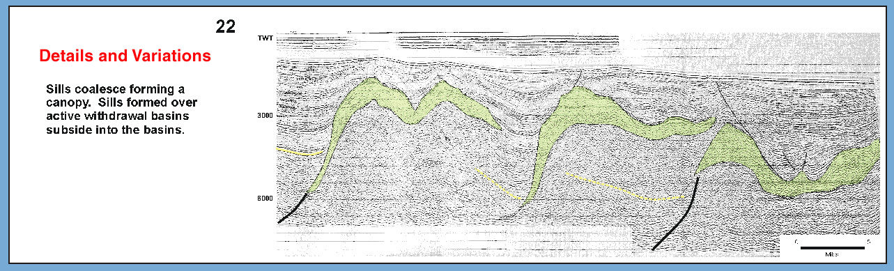