Click to view article in PDF format.
Himalayan Frontal Fold-Thrust Belt, NW India: Geometry, Structural Evolution, and Hydrocarbon Prospects*
By
Dilip K. Mukhopadhyay1 and Premanand Mishra2
Search and Discovery Article #10122 (2007)
Posted March 3, 2007
*Adapted from extended abstract prepared for presentation at AAPG 2006 International Conference and Exhibition, Perth, Australia, November 5-8, 2006
1Department of Earth Sciences, Indian Institute of Technology, Roorkee 247667, UA, India ([email protected])
2Premier Oil, New Delhi, India
The frontal part of the 2400 km-long and arcuate Himalayan Mountain belt is traditionally divided into three lithotectonic zones (Figure 1). From north to south, these are: (1) High Himalaya Crystalline Zone (HHCZ) composed of highly deformed and metamorphosed rocks of Precambrian age, (2) Lesser Himalaya Zone (LHZ) with a sequence of Upper Proterozoic to Lower Palaeozoic sedimentary rocks, and (3) Sub-Himalaya Zone (SHZ) consisting of Tertiary sedimentary rocks deposited in front of the rising mountain front. Each of these lithotectonic zones are bound on either side by longitudinally continuous and supposedly intracontinental thrusts, such as Main Frontal Thrust (MFT), Main Boundary Thrust (MBT), and Main Cental Thrust (MCT) (Figure 1). These thrusts are thought to be splays from a gently dipping detachment. Several oil/gas fields have been discovered during the last 125 years in the Himalayan FTB in Pakistan and Assam-Arakan FTB in northeastern India. However, no commercial oil/gas discovery has been made in the intervening areas in India, Nepal, and Bhutan. This is intriguing, particularly for the NW Himalayas, where many oil and gas seeps are known since historical times. We have undertaken a serial balanced cross section approach in a sector in the NW Himalayas to understand the subsurface structural geometry and evolution of the FTB. The Nahan salient, focus of the present study, is flanked by Kangra and Dehra Dun re-entrants in the NW Himalayas. We have constructed three serial balanced cross sections in the Nahan salient. In addition, one balanced cross section each on the flanking re-entrants have also been constructed (not described here). In this article, we describe the structural details in the Nahan salient. We expect that this and similar studies may help us to identify structural plays for detailed hydrocarbon exploration in the Himalayan frontal FTB.
|
|
Figure Captions
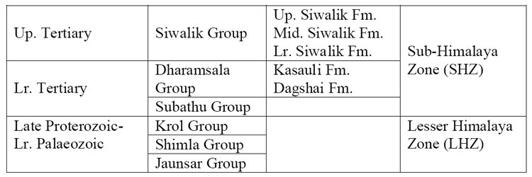
A simplified geological map of the Nahan salient and the locations of the lines of cross sections are shown in Figure 2. A simplified stratigraphy of the area is as follows:
It is generally considered that the three rock groups; i.e., LHZ, lower SHZ (i.e., Subathu- Dharamsala), and upper SHZ (i.e., Siwalik), are completely separated from each other by tectonic surfaces on the surface as well as in the subsurface. However, the geological map shows that this is not strictly true. Siwalik rocks occur within lower SHZ, and lower Tertiary rocks occur within LHZ. In addition to the two regionally important thrusts, viz., MFT and MBT mentioned above, a large number of map-scale thrusts are present in the frontal FTB. A number of large-scale anticlines and synclines are also present. The surface traces of thrusts and axial traces of folds are approximately parallel to each other. Statistical analyses of dips of bedding planes and axial planes of small-scale folds suggest that the rocks of both the SHZ and LHZ were deformed under a single, continuous deformation episode. For these reasons, we place the LHZ along with the SHZ rocks in the cover sequence and consider the crystalline rocks of the HHCZ as the basement. Therefore, the SHZ and LHZ together constitute the frontal fold-thrust belt (FTB) in the Himalayas. The deformation pattern in this belt is characteristic of thin-skinned tectonic setting, although LHZ is made up of Proterozoic sedimentary sequence.
The balanced cross sections have been constructed essentially using geological map and dip domain data. Two available seismic reflection profiles from this area are about 40 years old and are of rather poor quality. We have used these profiles only to constrain the depth and dip of the detachment. Both forward and inverse modelling were carried out during section construction. For each thrust, several fault-related fold models were constructed using dip-domain data in order to generate admissible structures (forward modelling). Several cross sections were then constructed using different combinations of these models and checked for viability or balance (inverse modelling). Departing from usual practice, we restored deformed-state cross sections in discrete steps; at each step we restored only one fault and ensured that the section remained admissible and viable at every step of restoration. This allowed us to work out the admissible geometry and sequence of thrust development and also to estimate slip on each fault at each stage of fault development.
The three cross sections from the Nahan salient are shown in Figure 3. In all the three sections the geometry of faults and fault-related folds increase in complexity from foreland towards hinterland. Based on the degree of complexity, the sections can be segmented into three transverse parts. The area towards the foreland lying between the MFT and the BiT and occupied dominantly by Siwalik rocks shows rather simple structural geometry. Widely spaced thrusts with simple fault-related folds are characteristic features in this segment. The MFT has flat-ramp-flat trajectory in the Subathu and Morni sections. The ramp anticlines in the hangingwall of the MFT in these two sections have the geometry of fault-bend folds. The MFT in the Nahan section is, however, emergent. Fault-propagation folding and low-angle breakthrough are present in the hangingwall of the MFT. The faults immediately NE of the MFT, viz., Nalagarh thrust (NaT, Subathu section), Bisiankanet thrust (BkT, Morni section), and Paonta thrust (PaT, Nahan section), have varying geometry of hangingwall structures. The homoclinal sequence in the hangingwall of the NaT represents a much-eroded fault-bend fault with out-of-sequence breakthrough along ramp. The Haripur thrust (HrT) is a diverging splay from the NaT. The surface dip-strike data have been used to model a blind thrust (BkT) in the footwall of the PaT. Multibend fault-bend folding is associated with BkT in both the Morni and Nahan sections. In the area between the BiT and the MBT, occupied dominantly by the rocks of the Subathu-Dharamsala Groups, the structural geometry becomes more complex. Here the linked thrusts trace thrust systems (Bilaspur thrust system) that approximately define leading imbricate fans (Nahan and Morni sections) or a buried hinterland-dipping duplex (Subathu section). The structural setting towards the hangingwall of the MBT is extremely complex. Low ramp spacing, folded thrust trajectories, interference of axial surfaces, and breached horses are the characteristic features in this area. The ‘LHZ thrust system’ (Figure 3) can be best described as stacked-up horses. The rocks of the LHZ dominantly occupy this area. From the foregoing description it is obvious that the frontal FTB can be partitioned into three segments occupied dominantly by Siwalik, Subathu-Dharamsala, and LHZ rocks, occurring successively away from the foreland. These three segments show distinct structural styles with structural complexity increasing from foreland towards hinterland. Some of the thrusts and fault-related folds can be traced in all the three sections, but others cannot be correlated. Some of the thrusts are emergent in one section but are blind or are absent in other section(s). Also the geometries of fault-related folds vary from section to section. The overall structural evolution of the area cannot be explained by a simple piggy-back sequence of foreland propagating thrust system giving rise to imbricate or schuppen structure (Figure 3). All the three sections have been restored successfully. We restored the sections in discrete steps. In other words, one fault was restored at a time and in opposite sequence in which they developed; i.e., the last fault to develop was restored first. The sequence of development of the structures was derived through forward and inverse modelling. All the in-sequence thrusts have “correct” trajectories in the restored sections in the sense that they have gentle to moderate dips towards the hinterland. Some of the out-of-sequence thrusts, however, have steep, overturned or zigzag trajectories in the restored sections. This is permissible because many of the out-of-sequence thrusts truncate previously formed thrusts. A model best describing the structural evolution in the Nahan salient is the one in which a foreland propagating, in-sequence thrusting event was followed by out-of-sequence thrusting in an approximately break-back style. During the out-of-sequence movement, some of the ramps that formed during in-sequence thrusting were repeatedly reactivated, leading to very complex structural geometries, particularly in the LHZ. The shortening partitioned between the MFT and Chail thrust is 71% (or 72 km), 59% (or 50 km), and 67% (or 67 km) in Subathu, Morni, and Nahan sections, respectively.
In an area with such structural complexity, a thorough understanding of subsurface structural geometry is essential for hydrocarbon exploration. Geophysical methods of subsurface imaging, such as seismic reflection, on its own may not be able to resolve such complex geometry of structures. Rigorous structural modelling incorporating all available data and using techniques of section balancing may be able to delineate areas for intensive exploration. Based on our sections, a number of play types can be identified, where detailed exploration for hydrocarbons may be undertaken. These include (Figure 4):
Play type I: Ramp anticlines (fault-bend or fault-propagation folds)
Play type II: Stratigraphic pinchouts/wedgeouts
Play type III: Roof sequences of buried duplexes Play type IV: Subthrust structural highs formed due to breaching of anticlines or synclines by out-of-sequence thrusts.
|